
Aarhus Mini Maker Faire 2015

I 2014 blev der for første gang afholdt Mini Maker Faire i Danmark, nærmere bestemt i Aarhus. Vi var med dengang (dog kun om lørdagen), og da det blev annonceret at begivenheden skulle gentages i 2015, begyndte vi at forberede os.
Vi endte med at tage 5 personer afsted begge dage, og vi havde en bred vifte af projekter med:
Kørestolsrobotten, som vi også tidligere har fortalt om. I dagens anledning var der koblet en PS3-controller til, så den kunne styres trådløst. Den var et stort hit, især hos børnene, men også blandt mange voksne.

Det var svært at køre stærkt indendøre, men på et tidspunk fik vi lejlighed til at tage den med udendørs:
Senere gentog vi successen, hvor den blev filmet af en drone:
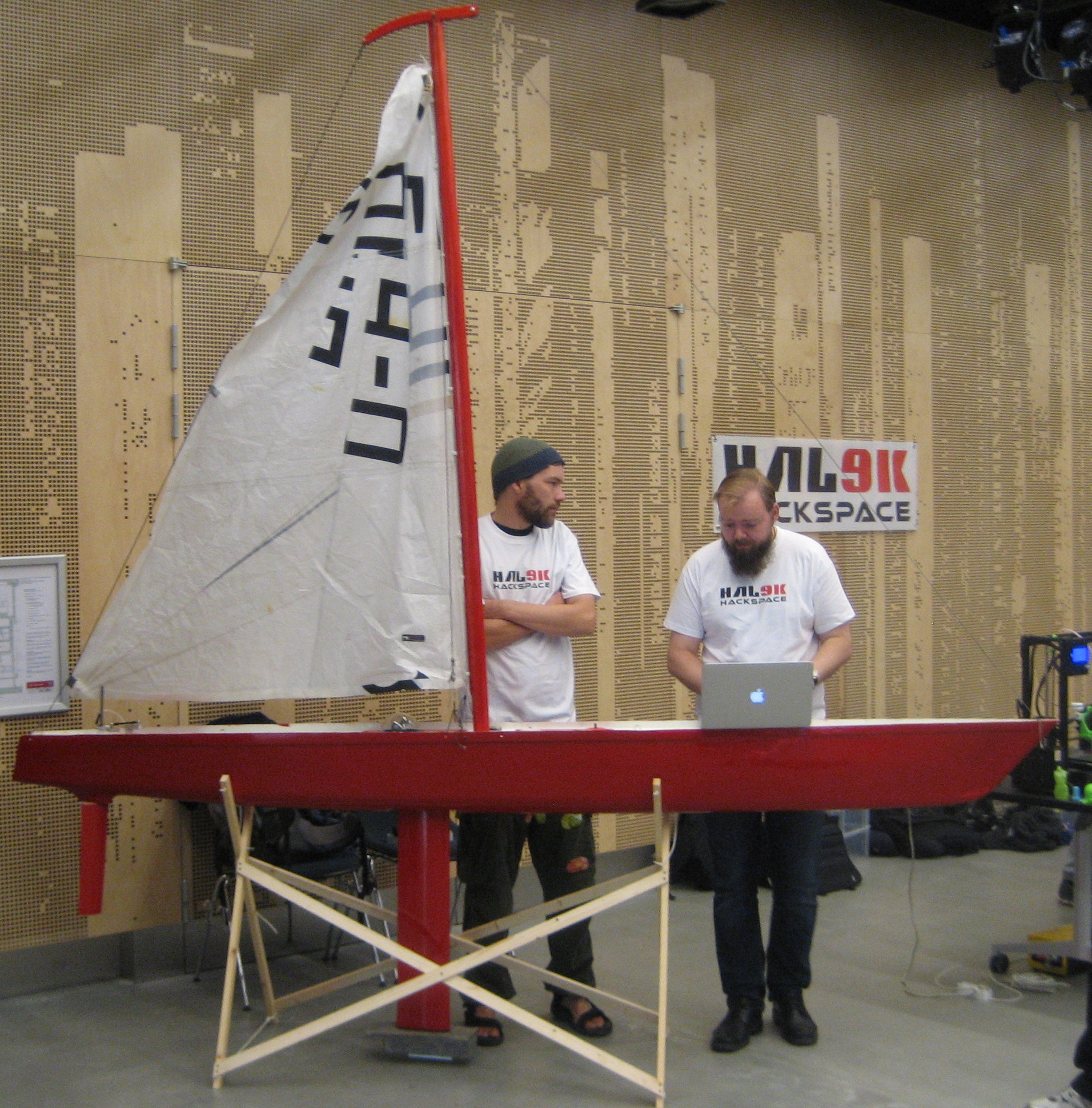
Sejlbåden – desværre havde vi ikke plads i bilen til vand, men Thomas og Jesper lavde et hurtigt hack, så roret kunne bevæge sig:
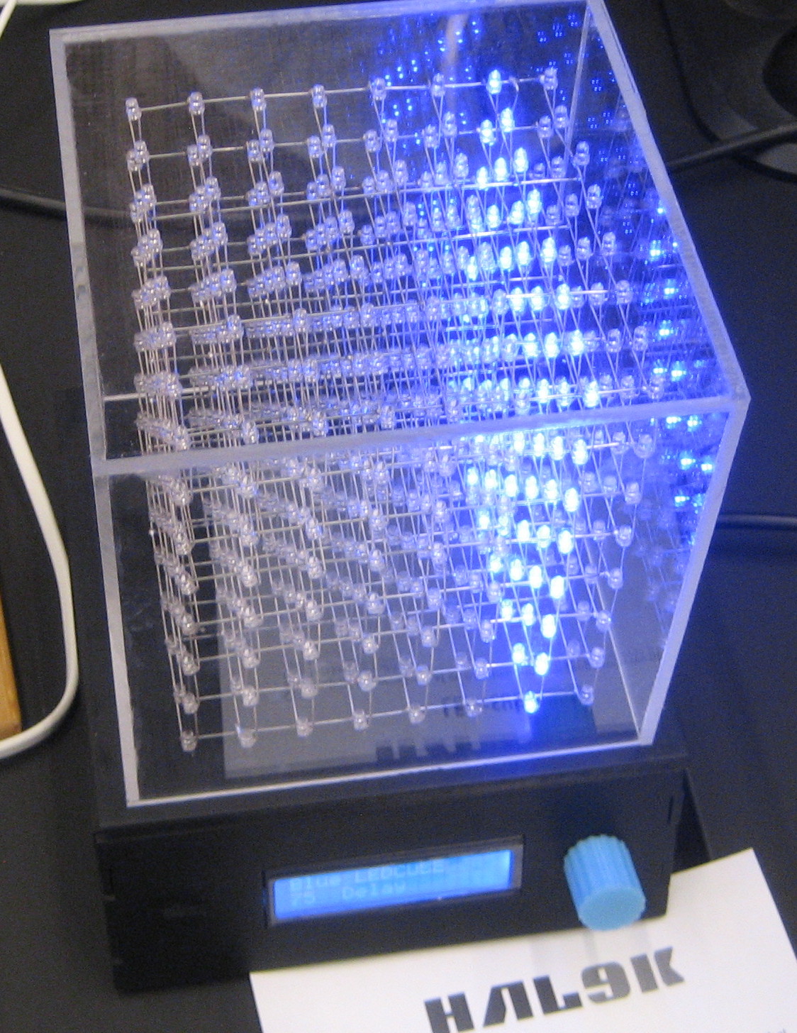
Anders’ LED-cube:
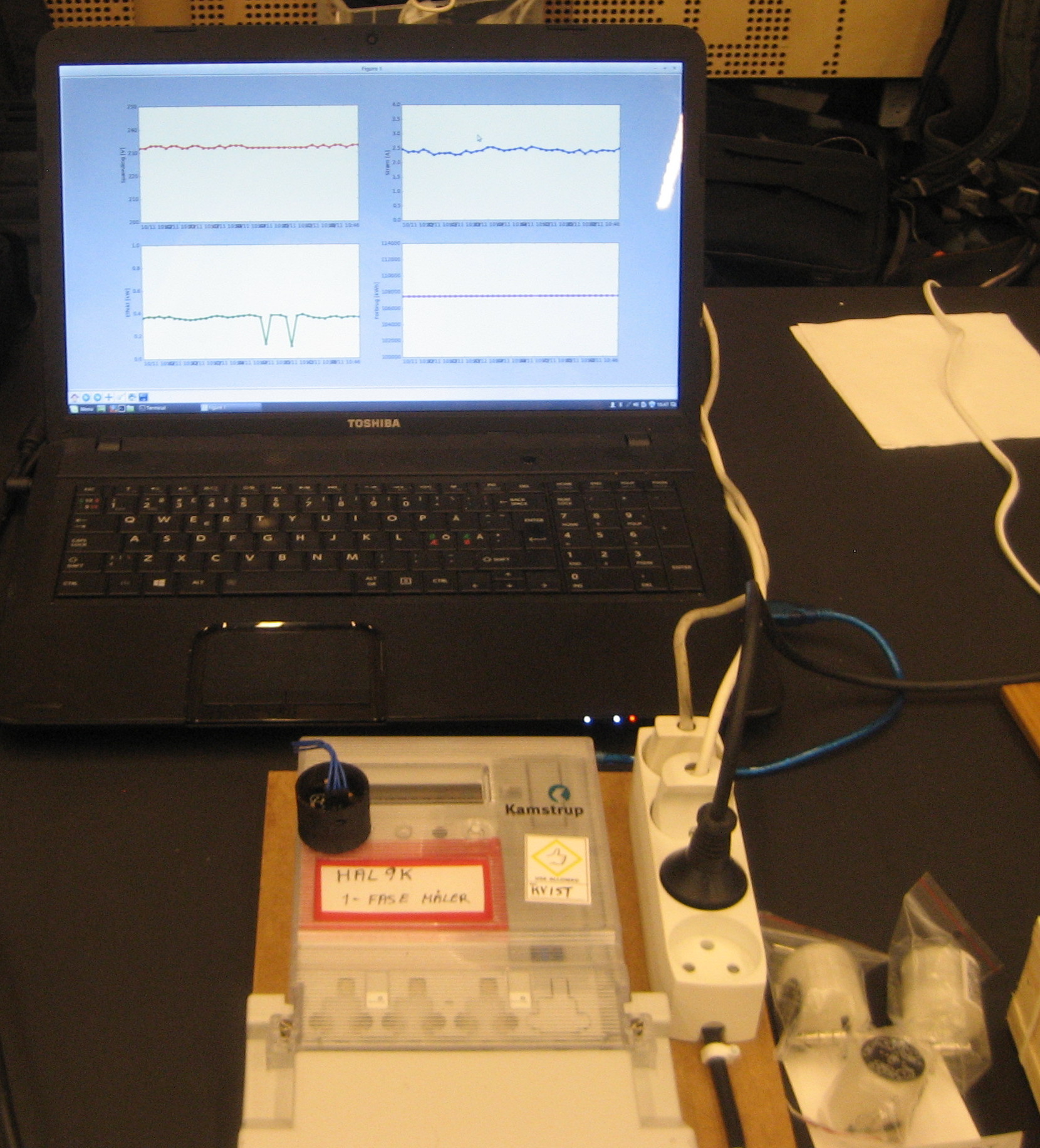
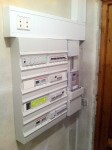
Demo af Kamstrup aflæsning: Vi havde taget PHKs PyKamstrup kode og tilføjet grafer vha. matplotlib. (Koden er her hvis nogen er interesseret).
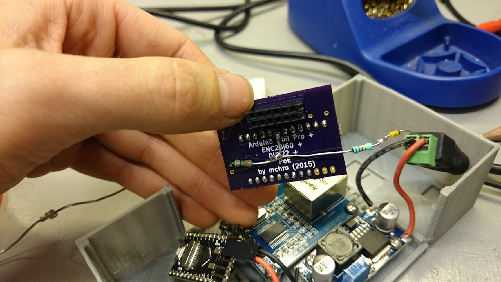
Vi havde lavet en håndfuld byggesæt, og vi fik faktisk solgt fire af dem.
Det uden sammenligning mest nørdede projekt var datatransmission over dåsetelefon: Ved hjælp af minimodem, en højttaler og en mikrofon sendte vi en ASCII-udgave af Star Wars fra en PC til en anden:
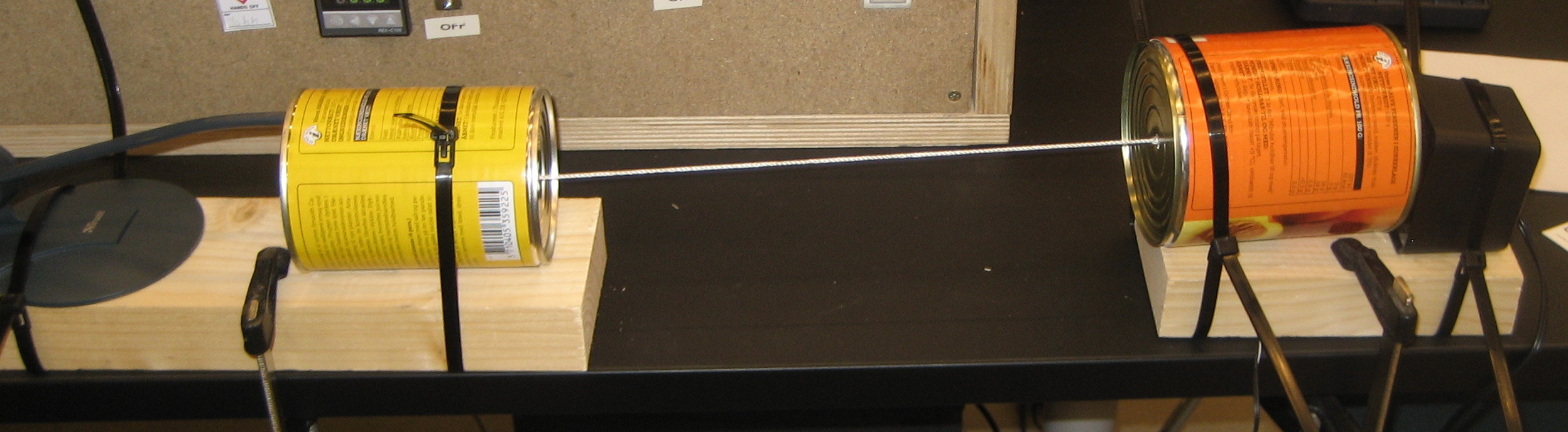
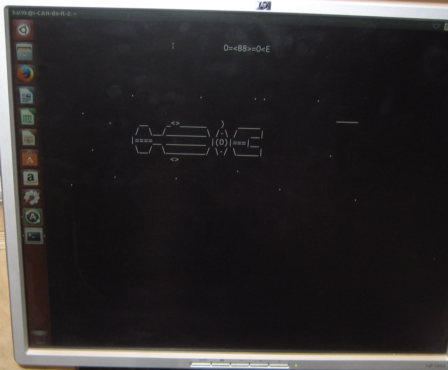
(Ja, hostname er I-CAN-do-it. Undskyld.)
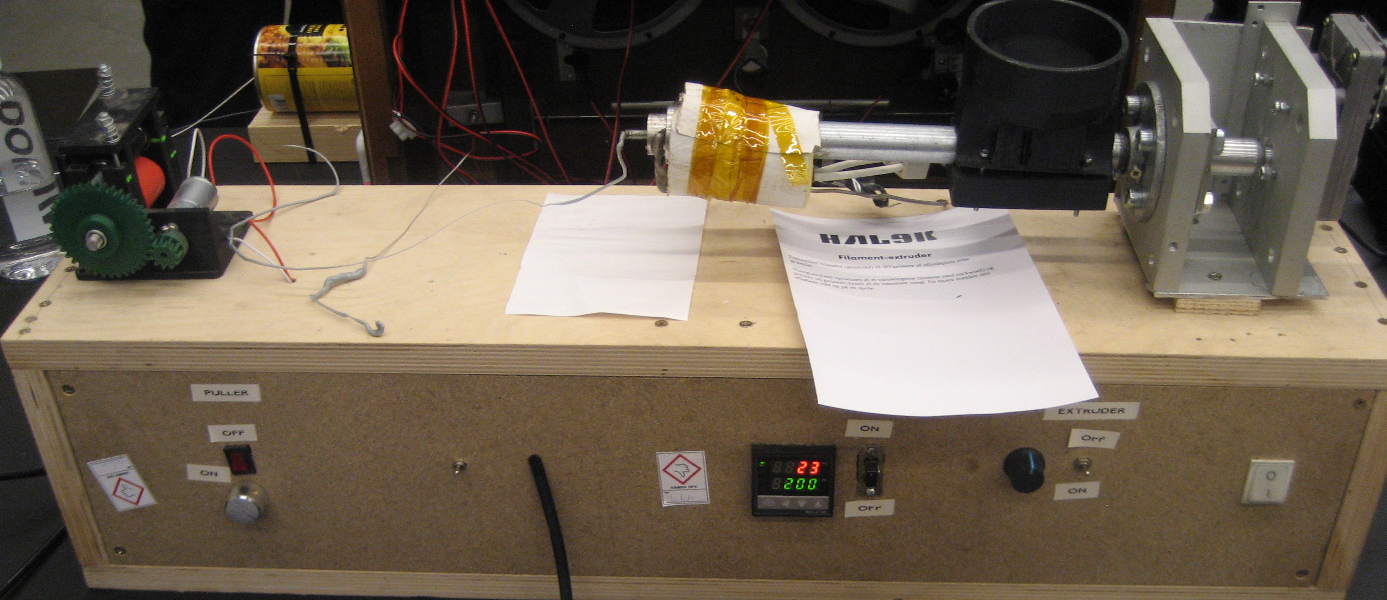
Vi havde også taget Johns filament-extruder med. Vi fik ikke ekstruderet så meget, men til gengæld kom der en forbi der vidste alt om ekstrudering af plast, så vi fik en håndfuld nyttige tips med hjem.
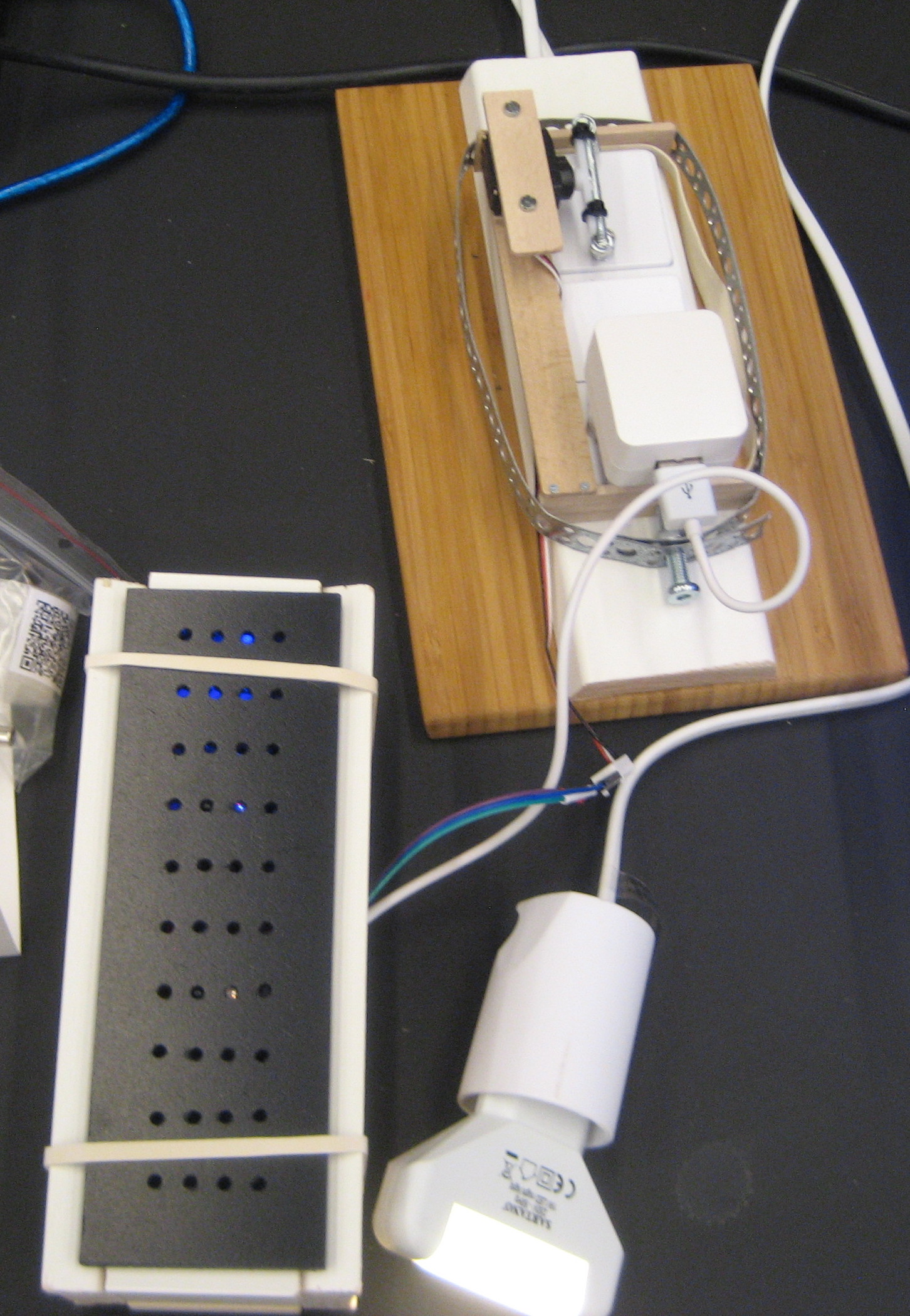
Daniel havde medbragt prototypen af sin berøringsfrie kontakt:
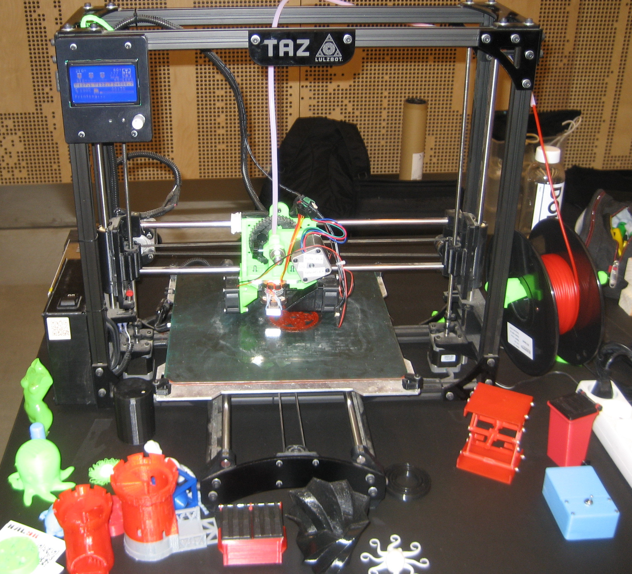
Naturligvis kan man ikke tage til MMF uden en 3D-printer, så den gode gamle Taz var også med, sammen med et udvalg af printede ting. Den mest populære af disse var uden en tvivl en “Useless Box”, som Anders havde lavet (den lyseblå kasse på billedet).
Desuden havde Jesper taget sin retroradio med:

Det var et par gode dage, hvor vi fik en masse besøgende og fik lejlighed til at hænge ud med vores fellow hackers i OSAA og Labitat.
![\[V_{out} = \frac{R_2}{R_1+R_2} \cdot V_{in}\]](http://blog.smartere.dk/wp-content/ql-cache/quicklatex.com-ee1f44dbd85a1cd2218265ee49ce5255_l3.png "Rendered by QuickLaTeX.com")
 to give
  , so
, so
![\[\frac{5}{30} = \frac{R_2}{R_1+R_2}\]](http://blog.smartere.dk/wp-content/ql-cache/quicklatex.com-f02f447533b604db627794c4ebd6140b_l3.png "Rendered by QuickLaTeX.com")
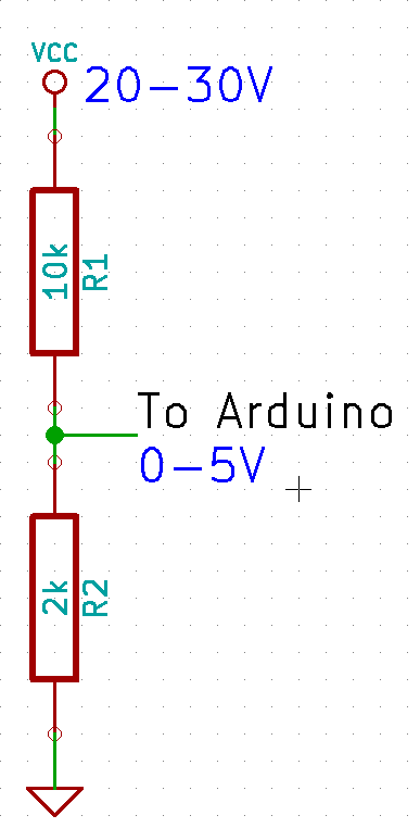
![\[ I = \frac{U}{R}\]](http://blog.smartere.dk/wp-content/ql-cache/quicklatex.com-93017fbe68496cbd35e880ea8ee1c4b5_l3.png "Rendered by QuickLaTeX.com")
![\[ I = \frac{30}{12000} = 0.0025 A = 2.5 mA\]](http://blog.smartere.dk/wp-content/ql-cache/quicklatex.com-6631b393a242838c08feb147241b12dd_l3.png "Rendered by QuickLaTeX.com")
 over the range.
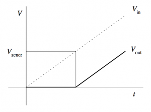
If only we could move the lower bound, so that 20V would map to 0V on the Arduino. A wild
over the range.
If only we could move the lower bound, so that 20V would map to 0V on the Arduino. A wild 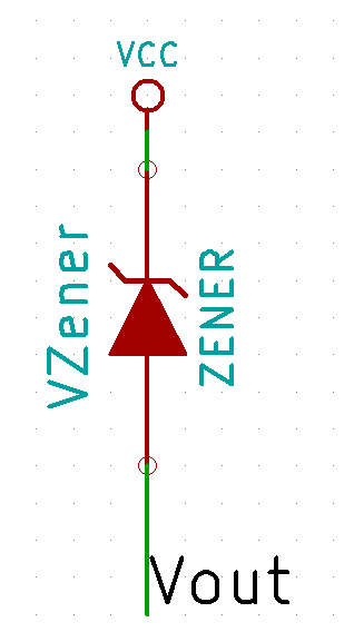
 The closest Zener diode I could find was an 18V of the
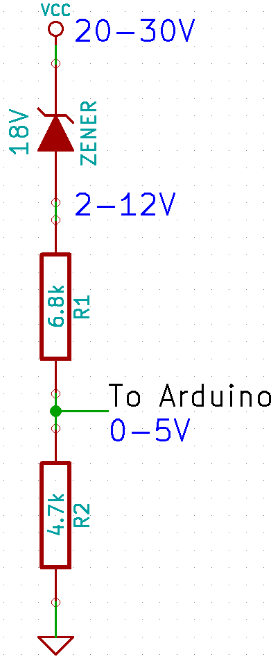
![\[Vcc = V_{in} / (4700/(4700+6800)) + 18 = V_{in} \cdot 2.4468 + 18\]](http://blog.smartere.dk/wp-content/ql-cache/quicklatex.com-2bf301ad44061de9fd4492ef666f33ad_l3.png "Rendered by QuickLaTeX.com")
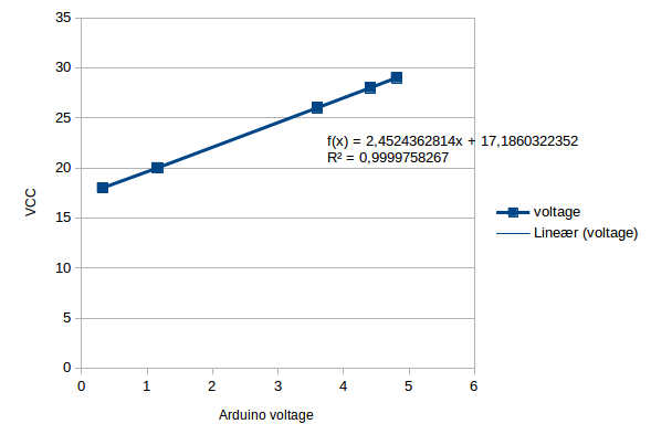
 ) as between 16.8-19.1V, so this is well within spec. Since this is just a one-off, I’m happy to just use the measured formula, as this will be more accurate.
The final precision should be
) as between 16.8-19.1V, so this is well within spec. Since this is just a one-off, I’m happy to just use the measured formula, as this will be more accurate.
The final precision should be  . The current should be around
  , which again is ok.


11 okt
5 Comments