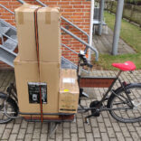
I dagens danmark hvor stort set alt hvad vi modtager af post foregår via digital post (E-boks) er det ikke så tit der kommer post i postkassen (med mindre man får mange små Kina pakker 😉 ) så for at undgå at hele tiden når jeg tjekker postkassen om der er noget eller ikke og så finder den tom. Bestemte jeg mig for at lave så jeg får en E-mail når der er nogen der åbner lågen til postkassen.
Så var spørgsmålet hvordan det skulle laves, det skulle være trådløst(WiFi), være fri for transformer/dc adapter da jeg ikke ville til at trække en ledning ud til postkassen!! Så derfor blev valget af microprocesser en ESP8266 ESP-12, da den allerede var klar til WiFi og skal bruge en spænding på ca 3.3 volt kan dog fint fungere på 4 volt, hvilket så også løste problemet med strøm der til, da jeg havde et par stykker af 18650 batterier til at ligge fra en gammel bærbar’s batteri.
Efter lidt oplæsning på ESP8266 funktioner på Github (Arduino core for ESP8266 WiFi chip), fandt jeg frem til funktionen ESP.deepSleep(microseconds, mode) hvor man kan putte EPS8266 i sleep mode indtil at GPIO16 er forbundet til RESET, denne funktion er smart da der så bruges så lidt strøm som over hoved muligt når den ikke sender data. I samme omgang fandt jeg ud af at man kan bruge den ADC(analog in) ben til at måle spændingen den får. Men for at det ville fungere skal ESP8266 omkonfigurere dens ADC hvilket gøres ved at putte “ADC_MODE(ADC_VCC);” øverst i koden. Så kan funktionen ESP.getVcc() bruges til at få spændingen i milivolt.
ESP8266’en blev placeret på et fumlebræt og forbundet til en FTDI så den kunne programmeres, og med en knap til at putte den i flashmode. Så skulle softwaren laves så den kunne sende en mail, så derfor tog jeg udgangs i en Arduino Ethernet sketch der sender en mail via smtp(non-SSL). Grundet at det kun virker med non-SSL smtp server kunne jeg ikke bruge min Hotmail til at sende mailen med da den kræver SSL eller TLS, men så faldt jeg over man med en Gmail kan sende en mail til sig selv eller anden Gmail ved at bruge “aspmx.l.google.com” som server med port 25 (link til kilde). De 2 før nævnte funktioner blev ind opereret i sketchen som var blevet ombygget til ESP8266, Så hver gang ESP8266 starter op sender den en mail til min gmail, og går der efter i sleep mode til at GPIO16 bliver sat til RESET.
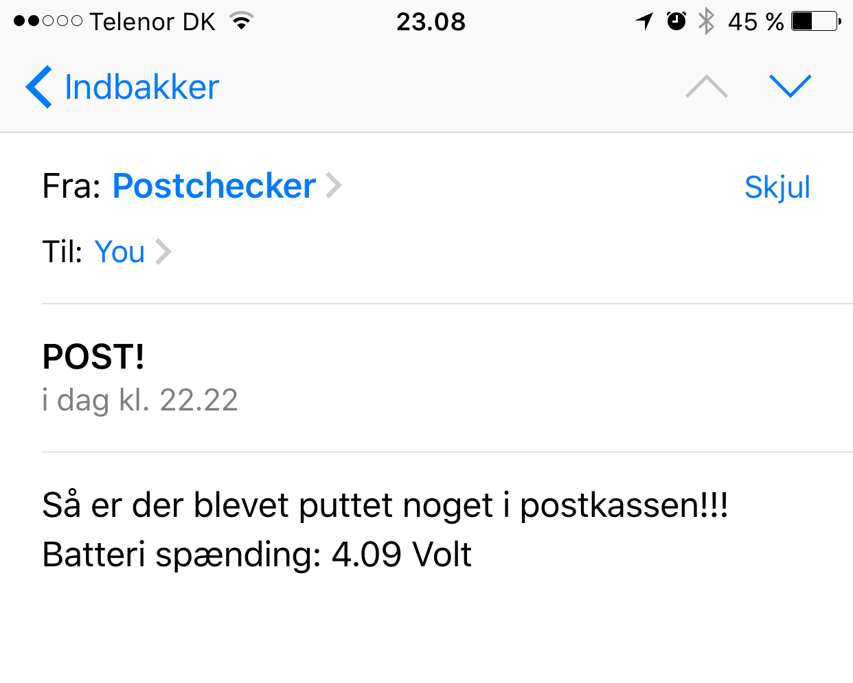
Mailen der kommer ser sådant ud.
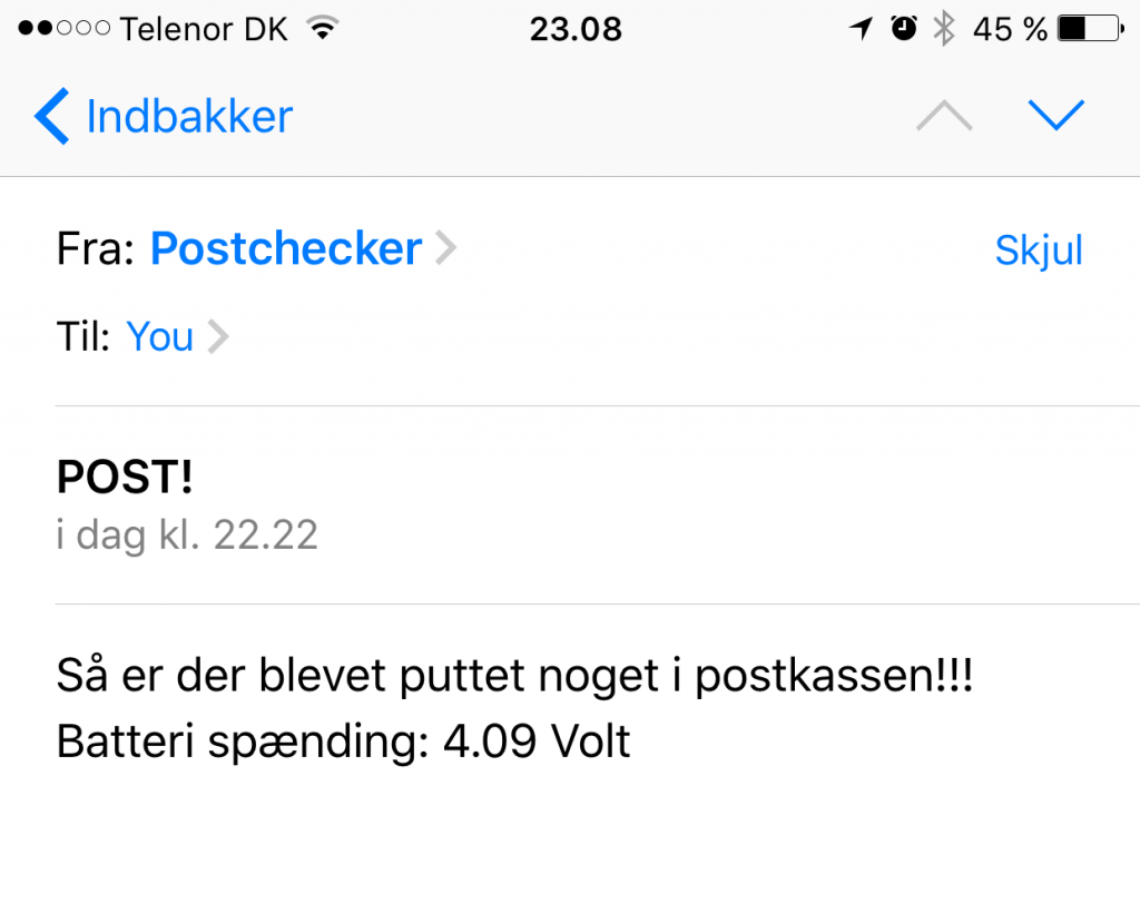
Mailen der modtages.
Efter at jeg havde testet at alt fungerede som det skulle, ville jeg til at lave et print som kunne holde alle komponenter så det blev pænt og overskueligt, men for at kunne lave det måtte jeg først lave et nyt eaglecad library da jeg ikke kunne finde en library for 3 af de komponenter jeg ønskede at bruge, ESP8266 ESP-12 monteret på breakout board, Dual 18650 batteri holder og en 18650 batteri charge modul.
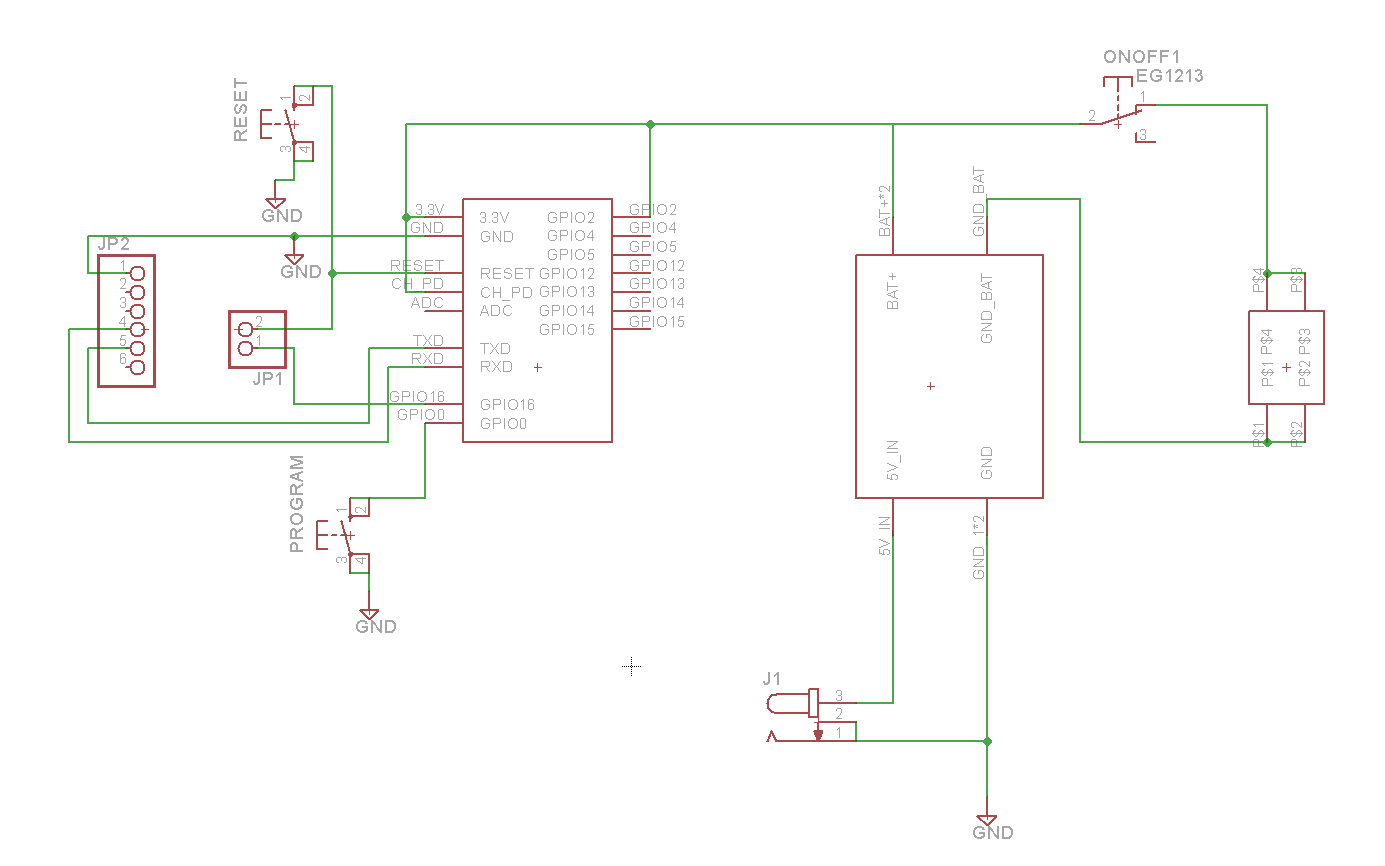
Nu kunne der så laves et diagram over hvordan det hele skulle forbindes
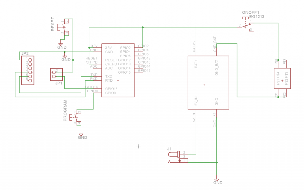
Ud fra dette diagram blev der lavet en board fil på 90×80 mm hvor alt blev presset ind på
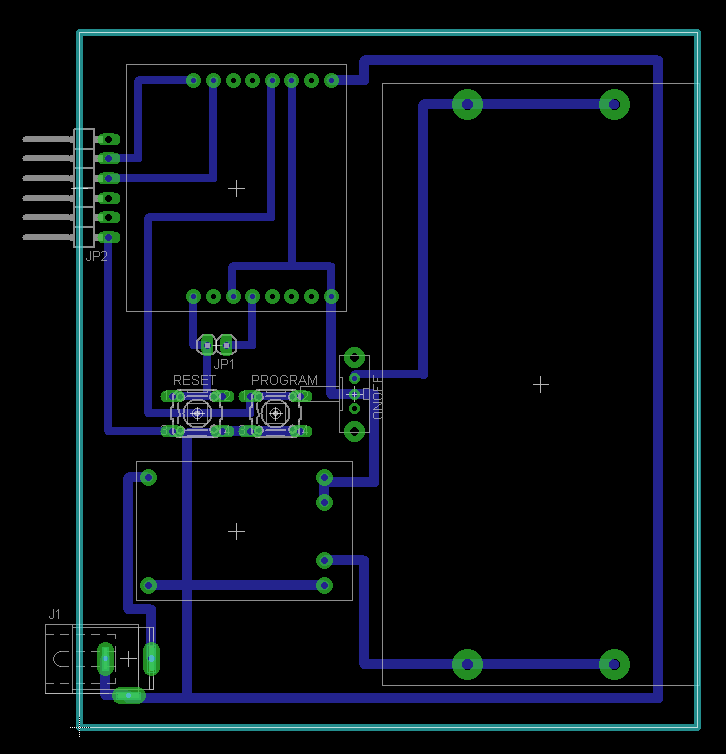
Da board filen var blevet færdig skulle der jo fremstilles et PCB, hvor jeg lavede en gcode fil med “pcb-gcode” et ulp script for at kunne fræse printet på vores Bundgaard cnc fræser. Det blev til 3 gcode filer, en med til fræsning med v-bit til alle banerne, en med alle huller og en til at skære PCB’en fri af en større plade.
For at få en pænere PCB valgte jeg at fjerne alt overskydende kobber med en hobbykniv ved at trække det af.
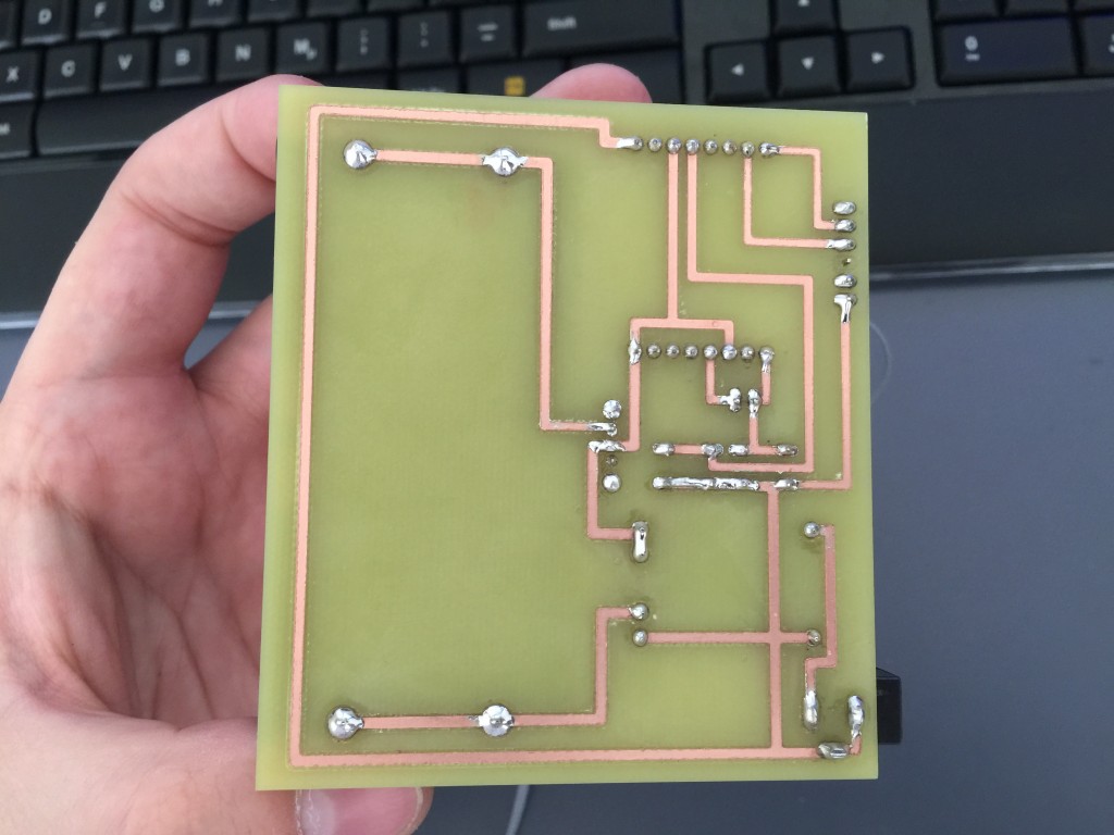
PCB efter overskyende kobber fjernelse og lodning.
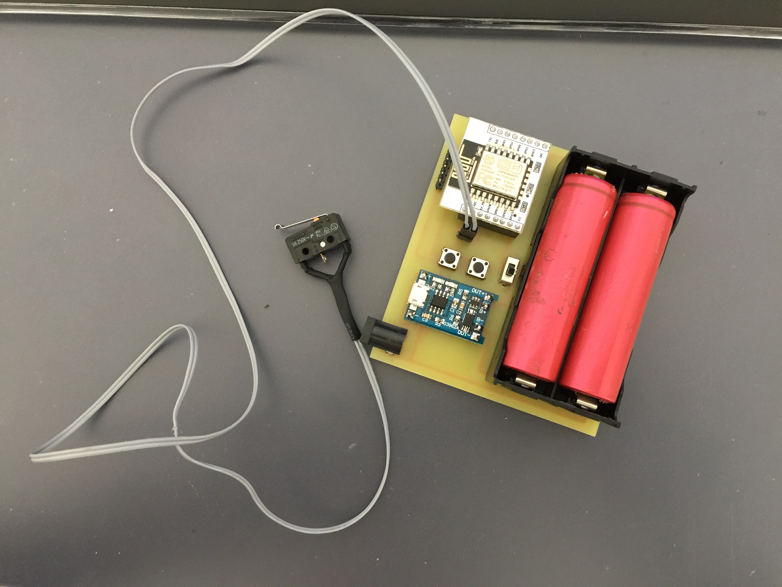
Nu kunne alle komponenterne så blive loddet på PCB’en. Samt microswitch (NC) sat på en 2 ledet ledning med dupon stik.

Komplet komponent liste:
- ESP8266 ESP-12 på breakout board
- Dual 186500 batteri holder
- 2 18650 genbrugsbatterier
- 18650 charge controller modul
- en on/off kontakt
- 2 trykknapper (til reset og flash mode)
- 14 (6+2+6) male pin header
- 16 (8+8) female pin header
- PCB power jack
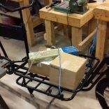
Klar til montering i postkassen. Det eneste der mangler nu er en 3D-printet boks der skal beskytte PCB’en og dens komponenter mod fugt og noget der kan falde ned og kortslutte noget!
Så nu er det slut med at kigge forgæves i postkassen!
Hvis du vil have eagle filer og koden til esp8266 kan de hentes her.


13 okt
0 Comments