Kategori HAL9k

25 maj

0 Comments

Ford 3000 Tractor Instrument Voltage Stabilizer – Mechanical PWM!

Af


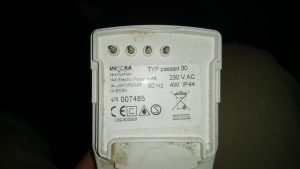
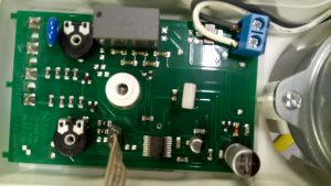
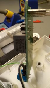
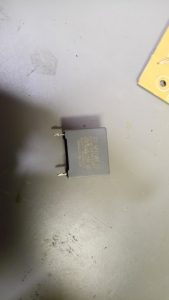
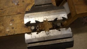
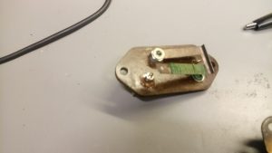
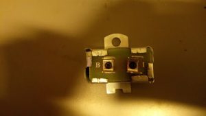
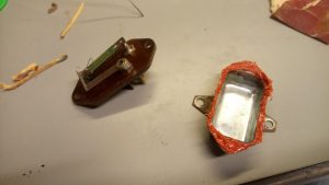
Some time ago we bought a nice used Ford 3000 tractor (3 cylinder diesel, Chief frontloader). It needed some work, and one of the items was a new wiring harness. After replacing all the wiring everything seemed to work fine, until one day all the instruments just died; this being a mechanical beast everything else kept working. After quite some investigation, I found out that the instrument fuse (the only fuse in the entire system) had blown. Replacing it just blew it again, so something was clearly wrong. This lead to taking out the so-called “instrument voltage stabilizer”, and disassembling it.

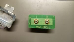
Apparently I had connected it in such a way that the arm had raised itself, and was now short-circuiting to the case. I had already ordered a replacement, but only got what was essentially a very expensive connection:

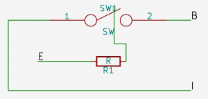
So, what was the mechanism actually doing, and is it essential? After some headscratching at Hal9k the conclusion was that it was essentially a mechanical PWM, with something like this diagram

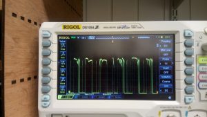
When the switch is touching the terminal current is flowing from the battery (B) to the instruments (I), but also to ground (E) through the resistor wrapped around the switch arm, causing the metal in the switch to heat up and lift. This breaks the connection, whereafter the switch cools down, and at some point makes contact again. Beautifully simple mechanism! Bending the arm back into position essentially fixed the device, and gave this waveform

I have seen the function described online as “pulsating DC”, which is actually quite accurate. So, I re-assembled the stabilizer with some sealant, inserted in the instrument cluster of the tractor, and it has worked perfectly ever since.

The only question is why it is done this way, if just giving a constant DC voltage from the battery also seems to work? I haven’t looked into it further, but my best guess is that the instruments are using coils to move the dials slowly, and that the PWM will heat up the coils less. In conclusion: If your voltage “stabilizer” is broken, you can probably do without it, or quite easily repair it.

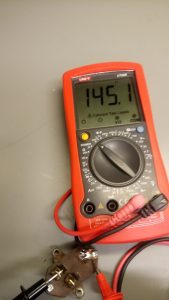
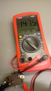
For reference, here are the resistance readings between B-E, and I-E:

Gemt under: Extern, HAL9k

Tags: ,

09 feb

2 Comments

Speaking “Pyt-knap” / “Never mind button”

Af

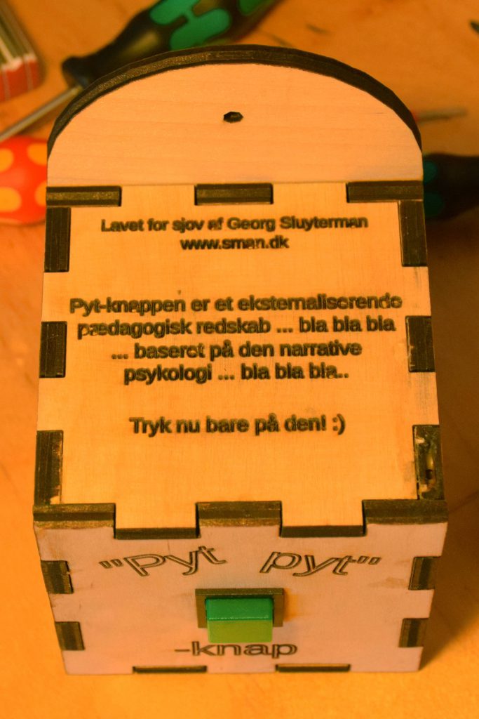
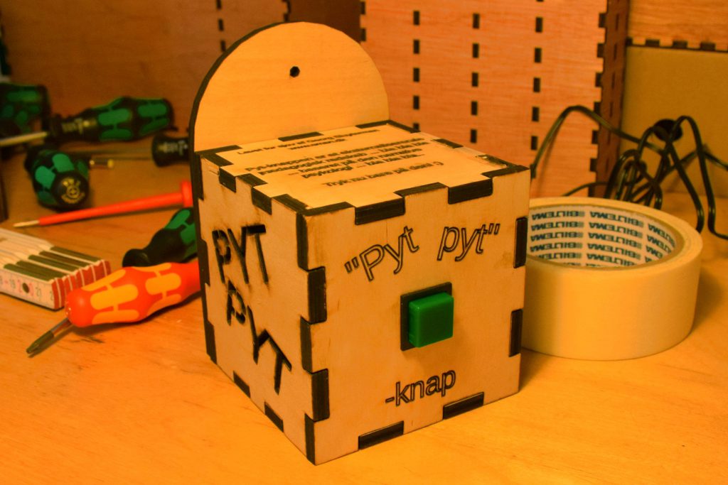
A woman working in a kindergarten told me about a button they had for the kids. Whenever there was some dispute between some kids, an adult could ask them to press the button, in order to easen the kids ability to act by the meaning of the danish word “pyt” (meaning something along the words “never mind”).

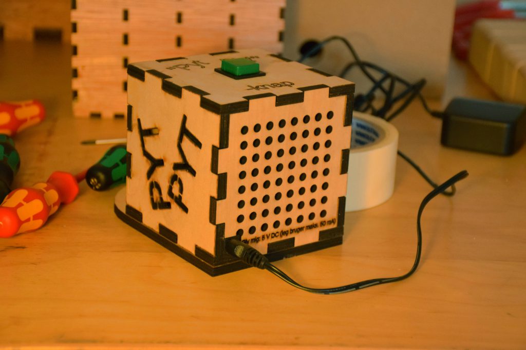
However it turned out turned out the button was not a button after all but just a sticker! I thought the idea behind the so called “button” and the usage of it was fun, so I decided to make one for the kindergarten.

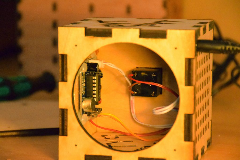
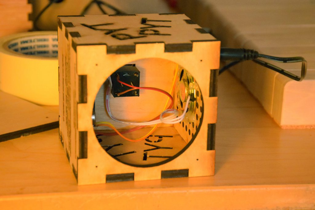
The solution was straight forward: Make a little box with a laser cutter, an isd1820, a button, a dc plug for the case, a lot of hot snot glue and a 5 V power supply. The box is made of 6 mm ply wood and measures 9x9x9 cm. The hole on the back is covered by the back plate where the screw in the wall is screwed in. To finish it all up I gave it two layers of varnish. If you want to build one your self, the OpenSCAD file is available here and an SVG (the green color should only be engraved) is available here (the green color in the SVG should only be engraved).

If I later on get a picture or a small video clip of the button in use in the kindergarten, I will update this post.

Pyt knap

28 jan

0 Comments

Reverse engineering Aduro Smart Response

Af

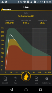
I have a fancy thermometer for my wood stove namely an Aduro Smart Response. The accompanying Android app basically shows a temperature graph, with guidelines as to whether the burning is optimal and when put in more wood. I have generally been content with the app: it is quite slow, but generally helps in more optimal burning. Recently however, the Android app has stopped working (something about connecting to a database), and this prompted me to start on a project I wanted to do for some time: get the data from the Smart Response unit into a database under my control.

The Smart Response unit uses Bluetooth Low Energy, and is powered by 3xAAA batteries (my batteries lasted for a year before replacing). Connecting to a BLE unit from Linux is quite easy, at least from the command line:

$ sudo hcitool lescan
LE Scan ...
B4:99:4C:25:12:B2 (unknown)
B4:99:4C:25:12:B2 Aduro demo
$ sudo hcitool lecc B4:99:4C:25:12:B2
Connection handle 3585
$ sudo gatttool -b B4:99:4C:25:12:B2 --interactive
[B4:99:4C:25:12:B2][LE]> connect
Attempting to connect to B4:99:4C:25:12:B2
Connection successful

hcitool is used to create a connection/pairing. gatttool is used to query the device interactively. Thereafter the device can be explored, to see which “handles” are available:

[B4:99:4C:25:12:B2][LE]> primary
attr handle: 0x0001, end grp handle: 0x000b uuid: 00001800-0000-1000-8000-00805f9b34fb #Generic Access
attr handle: 0x000c, end grp handle: 0x000f uuid: 00001801-0000-1000-8000-00805f9b34fb #Generic Attribute
attr handle: 0x0010, end grp handle: 0x0022 uuid: 0000180a-0000-1000-8000-00805f9b34fb #Device Information
attr handle: 0x0023, end grp handle: 0x0027 uuid: 0000180f-0000-1000-8000-00805f9b34fb #Battery
attr handle: 0x0028, end grp handle: 0xffff uuid: 0000ffb0-0000-1000-8000-00805f9b34fb # ???

The annotations on the right are mine; the UUIDs can be looked up under GATT services on the Bluetooth website.
For example, the battery status can be queried somewhere in the Battery handle group from 0x0023 to 0x0027:

[B4:99:4C:25:12:B2][LE]> characteristics 0x0023 0x0027
handle: 0x0024, char properties: 0x12, char value handle: 0x0025, uuid: 00002a19-0000-1000-8000-00805f9b34fb
[B4:99:4C:25:12:B2][LE]> char-read-hnd 0x0025
Characteristic value/descriptor: 5d # Battery level 0x5d = 93%

Now, the only unknown primary is from handle 0x0028 and higher. Let’s query those:

[B4:99:4C:25:12:B2][LE]> characteristics 0x0028 0xffff
handle: 0x0029, char properties: 0x0a, char value handle: 0x002a, uuid: 0000ffb6-0000-1000-8000-00805f9b34fb # 0x0a = R/W
handle: 0x002c, char properties: 0x10, char value handle: 0x002d, uuid: 0000ffb7-0000-1000-8000-00805f9b34fb # 0x10 = notify
handle: 0x0030, char properties: 0x10, char value handle: 0x0031, uuid: 0000ffb3-0000-1000-8000-00805f9b34fb # 0x10 = notify
handle: 0x0033, char properties: 0x02, char value handle: 0x0034, uuid: 0000ffb4-0000-1000-8000-00805f9b34fb # 0x02 = Read
handle: 0x0035, char properties: 0x08, char value handle: 0x0036, uuid: 0000ffb8-0000-1000-8000-00805f9b34fb # 0x08 = Write
handle: 0x0037, char properties: 0x08, char value handle: 0x0038, uuid: 0000ffb9-0000-1000-8000-00805f9b34fb # 0x08 = Write
handle: 0x0039, char properties: 0x0a, char value handle: 0x003a, uuid: 0000ffb5-0000-1000-8000-00805f9b34fb # 0x0a = R/W
handle: 0x003b, char properties: 0x08, char value handle: 0x003c, uuid: 0000ffb2-0000-1000-8000-00805f9b34fb # 0x08 = Write

The annotations on the right are again mine: they specify the char properties as looked up under “Characteristic Declaration”. Querying the char value handles gives some uninteresting values (0x00 bytes, etc.), but also some interesting ones:

[B4:99:4C:25:12:B2][LE]> char-read-hnd 0x002d
Characteristic value/descriptor: c4 01 03 01 fd 00
[B4:99:4C:25:12:B2][LE]> char-read-hnd 0x003a
Characteristic value/descriptor: 44 65 6d 6f 20 20 20 00 # 'Demo \x00'
[B4:99:4C:25:12:B2][LE]> char-read-hnd 0x0034
Characteristic value/descriptor: c3 01 ba 01 c4 01 27 00 c2 01 d1 01

Querying a bit outside also gives some very interesting strings:

[B4:99:4C:25:12:B2][LE]> char-read-hnd 0x002b
Characteristic value/descriptor: 41 64 75 72 6f 20 47 65 74 4c 6f 67 # 'Aduro GetLog'
[B4:99:4C:25:12:B2][LE]> char-read-hnd 0x002f
Characteristic value/descriptor: 41 64 75 72 6f 20 4c 69 76 65 56 61 6c 75 65 # 'Aduro LiveValue'

At this point I tried to look for values that changed, and also manipulating the device (temperature, playing with the damper that is connected with a microswitch). It turns out that 0x002d and 0x0034 changes values, but 0x002d changes the most. Is there a pattern?

Characteristic value/descriptor: c4 01 08 01 fb 00
[B4:99:4C:25:12:B2][LE]> char-read-hnd 0x002d
Characteristic value/descriptor: c4 01 1f 01 f3 00
[B4:99:4C:25:12:B2][LE]> char-read-hnd 0x002d
Characteristic value/descriptor: c4 01 3c 01 ec 00
[B4:99:4C:25:12:B2][LE]> char-read-hnd 0x002d
Characteristic value/descriptor: c4 01 5c 01 e2 00
[B4:99:4C:25:12:B2][LE]> char-read-hnd 0x002d
Characteristic value/descriptor: c4 01 9f 01 c3 00
[B4:99:4C:25:12:B2][LE]> char-read-hnd 0x002d
Characteristic value/descriptor: c4 01 0f 02 9d 00
#counting UP DOWN

Something is counting up, while something else seems to be counting down; this was while the temperature was cooling down. As 0x002d allows for notify, we can even ask for notifications by writing 0x0100 to 0x002d + 1:

[B4:99:4C:25:12:B2][LE]> char-write-cmd 0x002e 0100
Notification handle = 0x002d value: c5 01 43 00 2a 01
Notification handle = 0x002d value: c5 01 44 00 2a 01
Notification handle = 0x002d value: c5 01 45 00 2b 01
Notification handle = 0x002d value: c5 01 46 00 2c 01
...
Notification handle = 0x002d value: c5 01 f0 01 94 00
Notification handle = 0x002d value: c5 01 f1 01 94 00
Notification handle = 0x002d value: c6 01 00 00 93 00
Notification handle = 0x002d value: c6 01 01 00 93 00

In the end of the series I manipulated the damper. Trying to identify the temperature, the last 2 characters seems the most promising: values from 0x93 (147 C) to 0x012c (300 C) seem reasonable from what I have seen previously. The middle 2 characters always increase by 1, so it is probably a datapoint counter. The first 2 characters seems to increase by using the damper.

This was implemented in a small Python script, using the Gattlib, pyAduroSmart.py.

I hooked this into my home monitoring system (more on that in a later blog post), and now have a nice graph of the number of firings, and the temperature:

Gemt under: Extern, HAL9k

02 nov

0 Comments

Solder fume lamp

Af

DSC_0011

I needed something to remove the smoke when soldering and build this USB powered solder fume fan lamp with an ESP8266 arduino, WS2812b/Neopixels, a fan with an active coal filter and a PIR sensor.

See a short demo of the lamp on Youtube.

Scad/svg files are available on Thingiverse.

The case is lasercutted in 4 mm plywood.

When there is no movement beneath the lamp the fan turns off after e.g. 60 seconds (can be extended to e.g. 1800 when holding down the fan button) and the LED turns off after 1800 seconds of inactivity. The LED intensity can be dimmed by holding down the LED button.

Parts list:
* 4 mm plywood for the laser cutted case
* Ikea Forså lamp ( http://www.ikea.com/us/en/catalog/products/80146777/ )
* WS2812b / Neopixel strip (30 LED/m, 12 LED’s are used for the lamp. I bought it on Ali Express)
* Level shifter from 3.3 V to 5 V for the 3.3 V output from the PIR sensor (https://www.adafruit.com/product/757 I bougt it on AliExpress)
* 1.5 mF capacitor betwen +5 V and ground near the Neopixels, for evening out voltage drops and ripple from the USB power.
* PIR sensor (https://www.adafruit.com/product/189 I bought it on AliExpress)DSC_0057
* Fan (80 mm, 12 V. It was just laying around)
* Wemos D1 mini (https://www.wemos.cc/product/d1-mini.html)
* Wemos ProtoBoard (https://www.wemos.cc/product/protoboard.html)
* Wemos RelayShield for turning the fan on and off (https://www.wemos.cc/product/relay-shield.html)
* MT3608 DC-DC Step Up Power Module from AliE for the power for the 12 V fan
* Activated coal filter (adjusted the size with a scissor) (https://www.conrad.de/de/aktivkohlefilter-3teilig-toolcraft-79-7201-588546.html i bought it on AliE)
* two push buttons, connecting the pins from the ESP8266 to ground.
* USB cable
* A few strips, pig tail wires, bolt and nuts etc.

DSC_0056

The case is glued together with normal wood glue and the PIR sensor and the WS2812b Neopixel strips are glued against the case with cyanoacrylate. The DC-DC converter is fixed with a cable tie. The Wemos D1 mini is fixed with a small bolt through a drilled hole in the ProtoBoard. The capacitor and the level shifter is glued with a hot glue gun. Be aware that there is very little room for the boards and the wires. If I were to build it again I would make some more room. Also the “stack” of the Wemos ProtoBoard, D1 mini and RelayShield is higher than the fan + activated coal filter, so it sticks out of the top, which I think is fine. All the parts do not need to be hidden away for the eye to see :-)

The software is available at:

https://github.com/sman-dk/arduino/tree/master/solder_fume_lamp

Since the ESP8266/Wemos D1 mini has wifi it can be made controllable via your smartphone etc. At the time of this writing I have no use of this, so for now I have not implemented anything fancy yet :)

DSC_0065

IMG_3547DSC_0055

Power usage when the lamp and fan is active
Power usage when idle

19 feb

0 Comments

Hvorfor korrelerer min DC-spænding med solen?

Af

DC-spænding over 24 timer

I mit home-monitoring setup har jeg en AC-DC strømforsyning der laver DC-strøm og lader UPS-batterierne. Denne spænding overvåger jeg, som beskrevet i sidste blogindlæg. Grafen set for en typisk dag ser ud som ovenover. Der er en tydelig stigning i spændingen om morgenen og et tydeligt fald sidst på eftermiddagen. Det korrelerer forbavsende godt med hvornår solen står og og går ned. Her er data for 3 forskellige dage, overlagt med sol op-/ned-tidspunkt:

6sept

6. september – ufiltreret

26-10-2015

26. oktober – filtreret

21-12-2015

21. december – filtreret

Der er ikke noget forbundet til DC-forsyningen der trækker væsentlig forskellig strøm efter belastning (det der er forbundet er switche, router og Arduinoer), og intet der tænder/slukker efter tidspunktet. Temperaturen varierer ikke væsentligt i rack-skabet, og korrelerer ikke med spændingen:

temp-volt-oct

Temperatur og spænding, hele oktober. Spænding (grøn) på højre akse.

temp-volt-26oct

Temperatur og spænding, 26. oktober. Spænding (grøn) på højre akse.

Så det store spørgsmål er: Hvorfor korrelerer min DC-spænding med solen? Er det pga. solceller i nabolaget? Er det pga. gadebelysning der tænder/slukker? Gode bud modtages :-)

Gemt under: Extern, HAL9k

Tags: