Kategori HAL9k

29 sep

0 Comments

18650 Lithium-ion battery packs – 1S80P

Af

This is the considerations I did when building 1S80P 18650 battery packs, for a DIY powerwall.

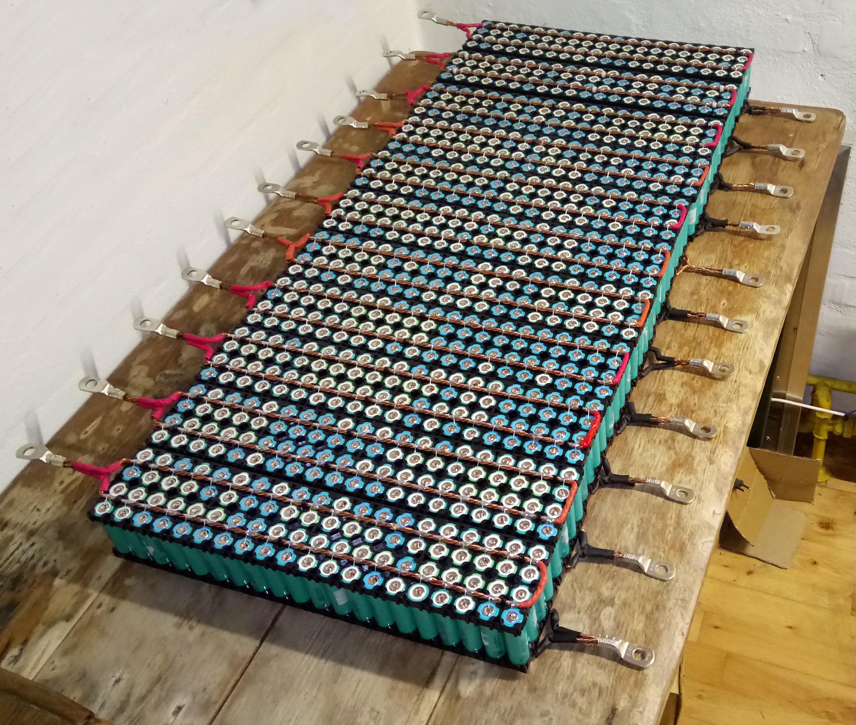
My design will go for 14 of these packs in series, for a nominal 48V system.

I wanted a design that was:

  • Very hard to short circuit, individual cell fuses, and generally as safe as possible
  • Mechanically stable
  • Balanced as much as possible
  • Expandable

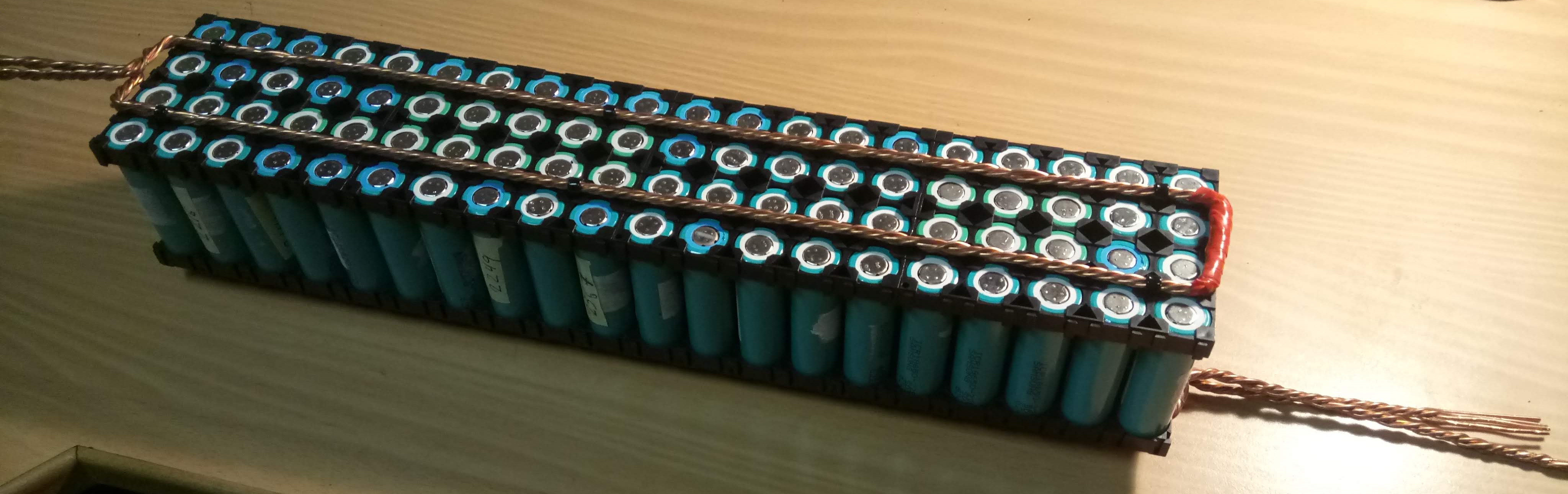
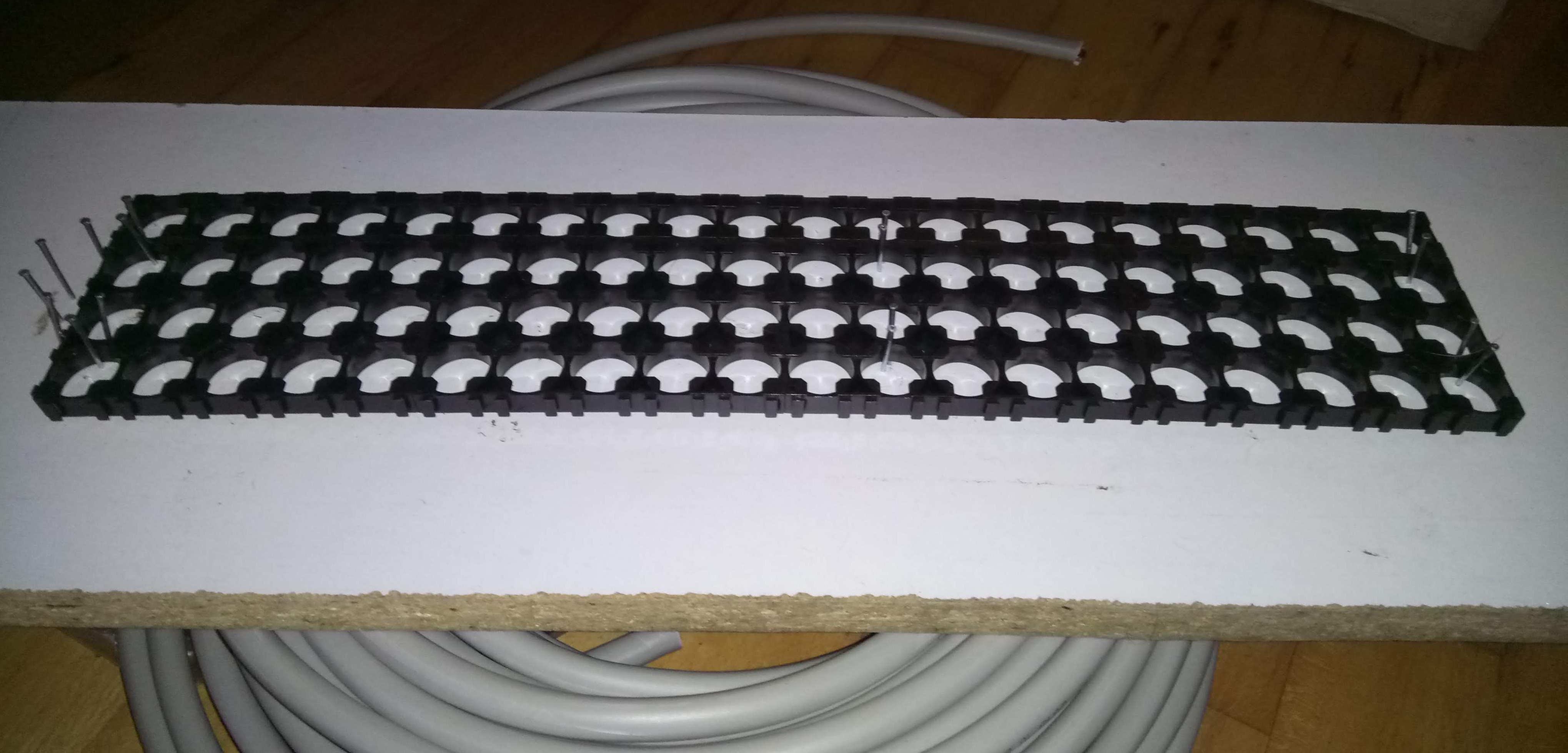
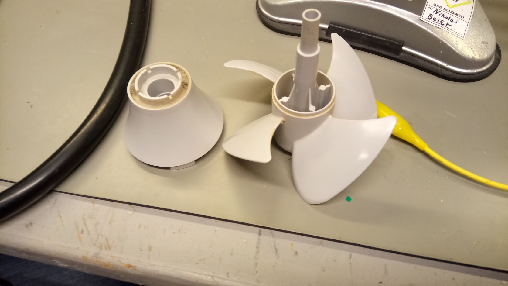
The design is basically 4 4×5 18650 holders for the top and bottom. The cells I used were all tested for capacity (all above 2000 mAh) and self-discharge (all above 4,1V after several weeks/months), and are all Samsung cells. When assembling the packs I tried to mix the cells as much as possible: this should mean that on average the packs will be approximately the same capacity.

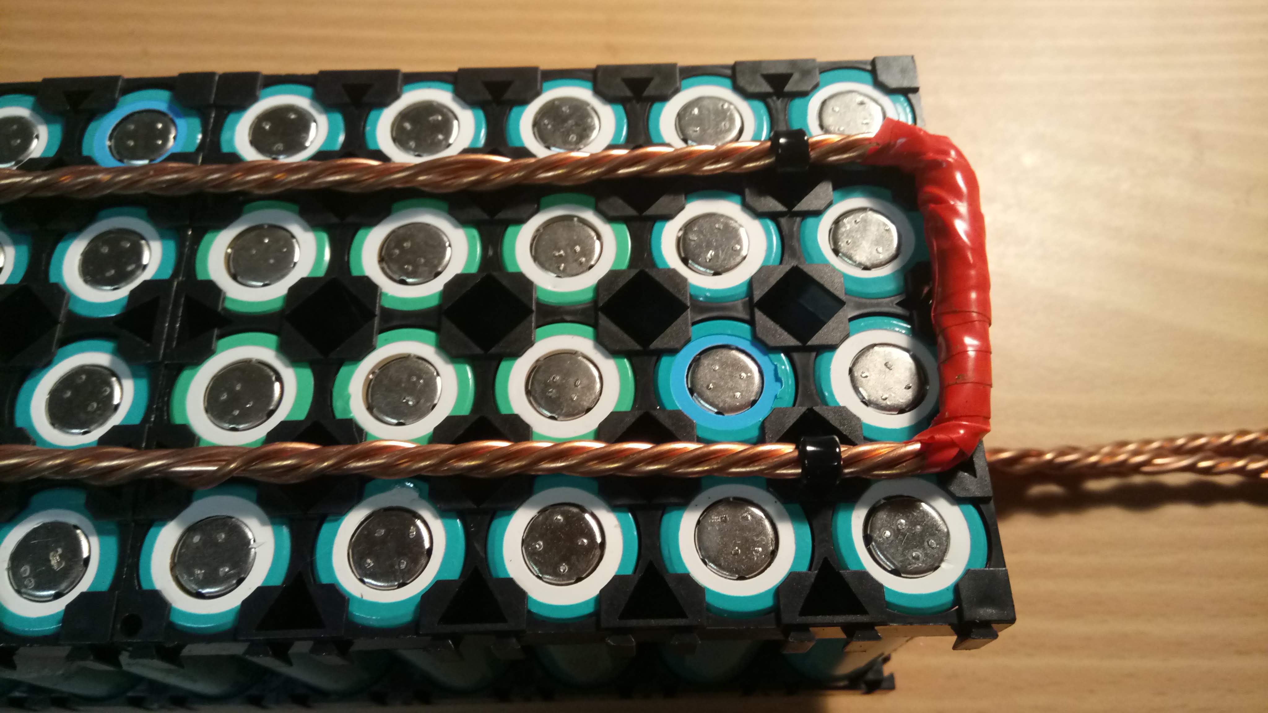
The packs have all the positive metal on the top, and the negative on the bottom. This means that any metal would have to touch both the top and the bottom, to short circuit the pack; this is not possible with a straight piece of metal. The connectors are going out on each side: if they went out the same side it would be possible to short-circuit them. Also, this will ensure that all the cells are discharged at the same rate: if they went out the same side the cells closest to the connectors would be loaded harder than the ones further away. This layout will not be a problem when they are put in series, they will just be alternating up-down. The busbars are shrink-wrapped on both ends, so only the connector is connected.

This means that the packs are impossible to short-circuit by themselves.

The packs are held together by 6 zip-ties: 2 at each end, and 2 in the middle. 5mm holes are drilled in the holders. The zip-ties go through the packs and around the busbars on each side.

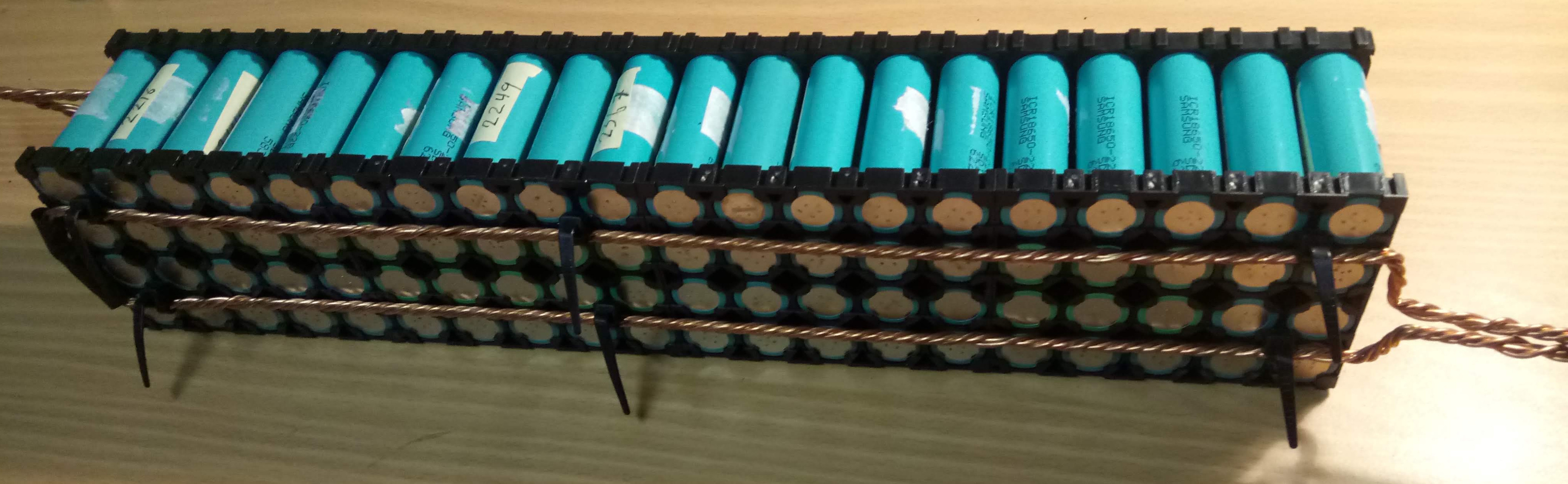
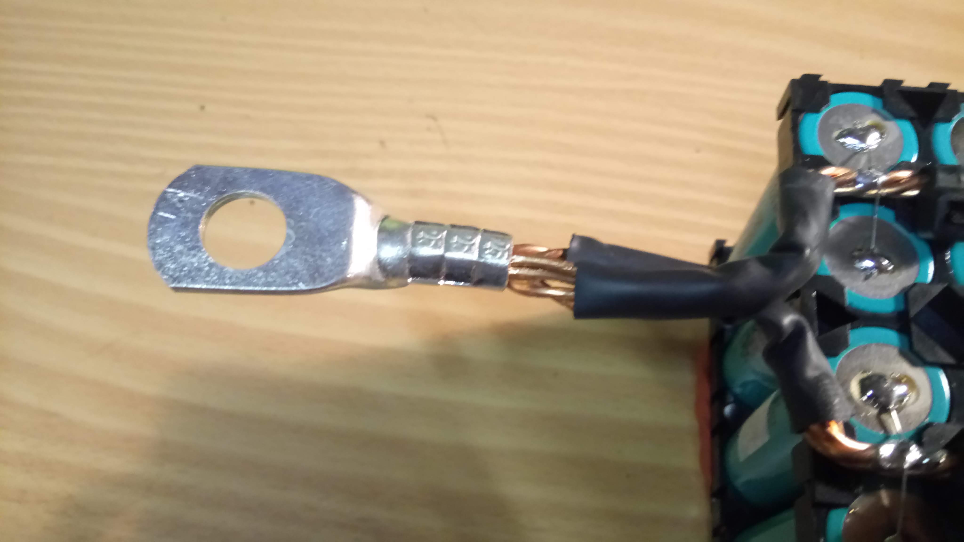
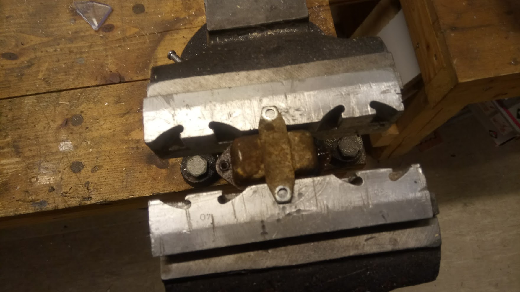
The busbars are 4 wires of 2.5mm² wires, that are extracted from a standard AC cable. They are twisted together using a bench vise, and a cordless drill. They are then pre-bent using a template.

The connectors are 25mm² cable lugs. The two ends of the busbar go into the lug, meaning 8 wires of 2.5mm², or 20mm² in total. Depending on the exact calculations, this should be good up to 80A-160A. I intend to load the packs with at most 80A, and normally much less, so this should be fine.

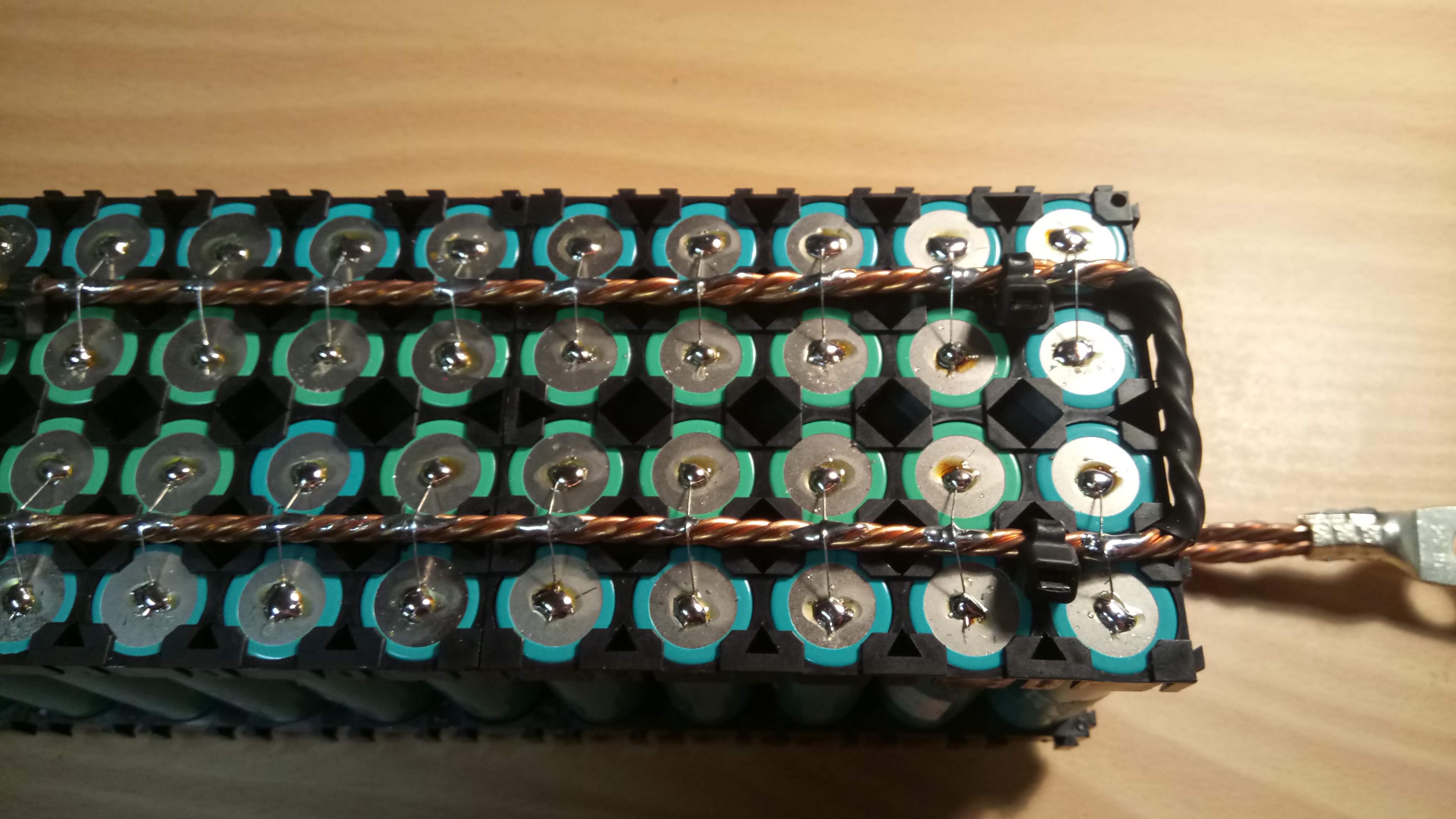
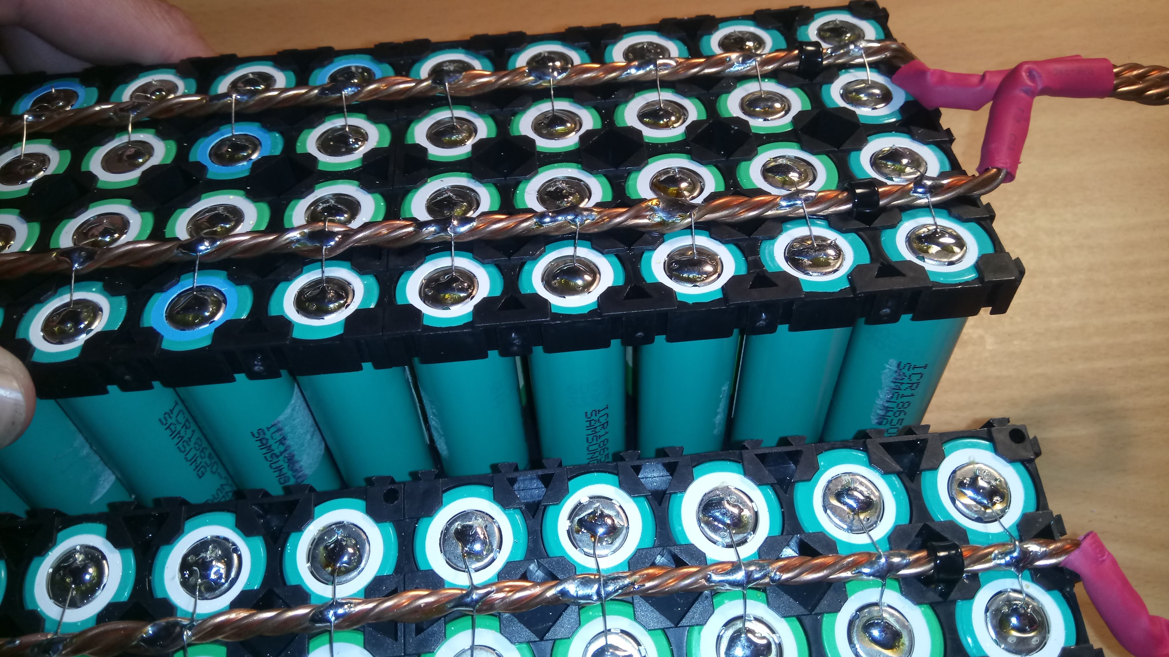
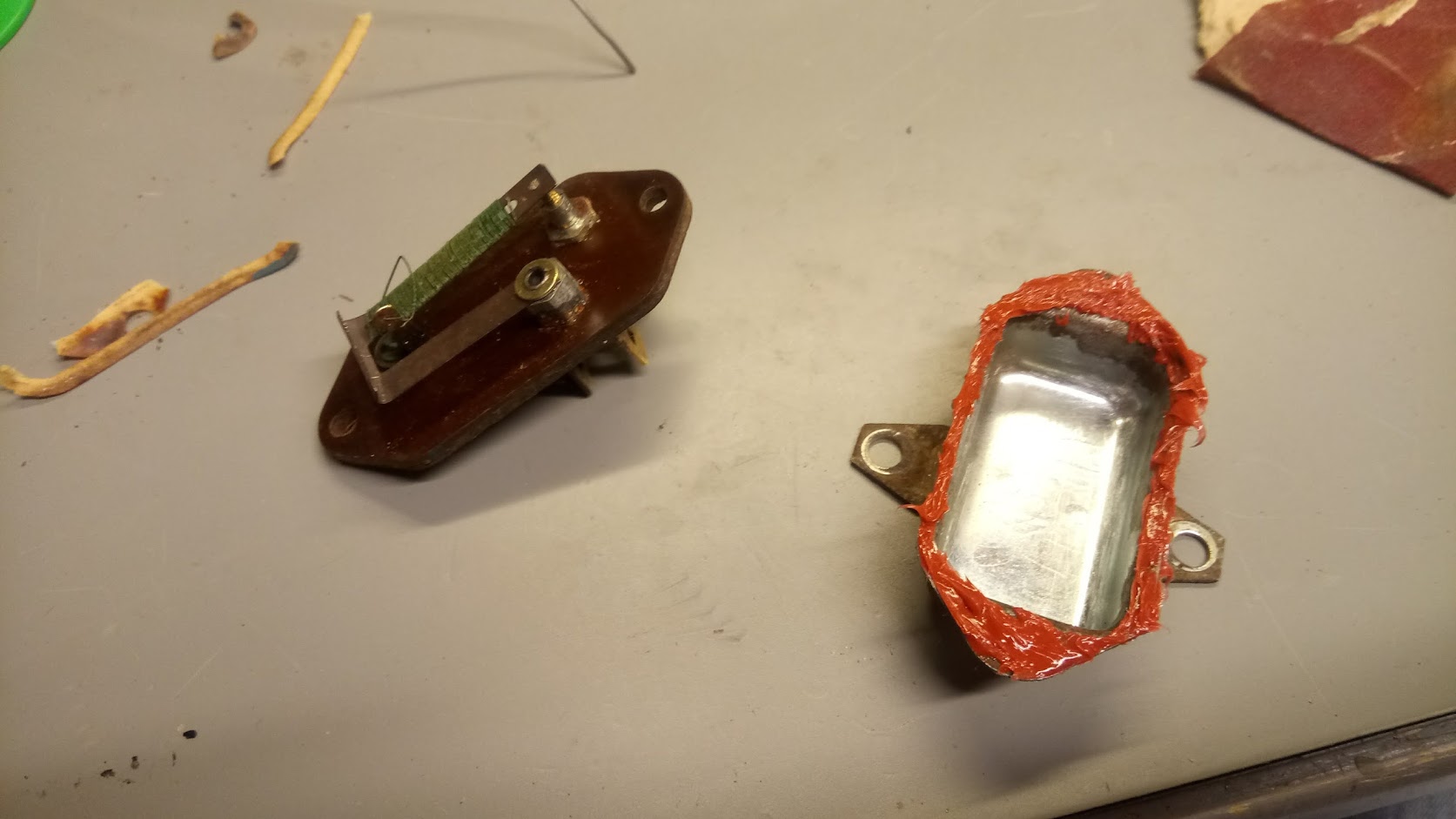
The cells are connected to the busbars by fuse-wires. I used legs from 1/8W resistors, from a batch I tested beforehand. The resistor legs blows at 5A after some time, and in a few seconds at 6A. This should be well within spec, since the fuse-wires are mainly intended to isolate cells that go short-circuit: in this case the other 79 cells will be delivering current to the one bad cell, and the fuse wire should blow very quickly. This is another reason to not build too small packs: you need enough current available that the fuses will blow quickly.

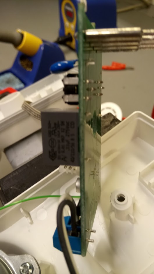
The fuse wire is soldered to the cells, and soldered to the busbars. I used good lead-based solder, I tried crappier and lead-free solder but the results were poor. The positive side is soldered at about 340C, while the negative needs a bit more heat at 350C. For soldering to the busbars I go up to 380C, and move around in a circle since heat management is very much needed.

One concern I have heard from several people is that the cells are losing capacity by soldering. I did a test by soldering a few cells, and leaving a few control cells unsoldered. Then I capacity tested all the cells for a few cycles to check if any capacity is lost. I was unable to find any capacity loss on the soldered or unsoldered cells, so for me that is “myth busted”.

The packs are prepared for a future extension to 1s160P or similar. The holders are all oriented in the same way, and in such a way that 2 80P packs should be able to click together side by side:

Each pack (or set of 2 packs if expanded) will get one Batrium LongMon. It should be fully capable of balancing such a system.

If the hivemind has any ideas or things I missed, I’m very interested in hearing about it!

Gemt under: Extern, HAL9k

Tags:

29 sep

0 Comments

Olimex A20-OLinuXino-LIME2 – A review after 4 years in service

Af

Last week my A20-OLinuXino-LIME2 one board Linux computer quit working, with a power supply issue. I looked up when it was purchased, and realised it had been in 24/7 service for almost 4 years. I guess that is a good excuse to do a little review. It even turned out that it the board was fine, but the AC-DC power supply brick could not supply enough current anymore.

The relevant specifications of the board, for my uses, are basically:

  • Dual core 1 GHz ARM Cortex-A7
  • 1 GB memory, 1 Gbit ethernet, SATA connector
  • LiPo battery connector/charger for UPS functionality

The Lime2 has been tasked with running my home monitoring system, consisting of a Debian installation with a Graphite backend, a Grafana frontend, and a ZoneMinder installation. The Graphite database is running on a software RAID0 of two disks (one on SATA, one on USB): in the beginning it was two spinning disks, but after a few years the random 2.5″ laptop disk I was using crapped out, so it was upgraded to a Samsung SSD. The power budget is strained more or less to the max with two spinning harddrives: The system was only able to boot if the battery was connected, presumably because the voltage would otherwise drop for the startup torque. This problem went away after switching to a SSD.

Software wise the system started out with the Debian supplied by Olimex on a SD-card, a Debian pre-Jessie with a custom SunXi kernel. This system was reasonable, but did experience random hangs after some time of use (I belive I found a bugreport back in the day, but am unable to refind it now). The system was later upgraded to a Debian Stretch with a 4.9 kernel from stretch-backports, that supports the SunXi chipset enough for my uses. The upgrade was rather involved,  requiring the correct kernel image, a custom U-boot script and the correct device tree file. Something did of course go wrong, at which point I got to be familiar with the serial console of the Lime2: there is a convenient 3 pin header, that gives access to a TTL serial. Using the serial console, I was able to identify the mistake and correct it. After the upgrade the system has been rock-stable.

The system has been handling the load reasonably: The 1GB of memory is constraining, there is not really any more free memory. The processor is only really strained by the motion detection in ZoneMinder, which uses more or less one core per camera. This will hopefully be optimized a bit, as ZoneMinder is being optimized for the ARM instruction set. Handling only the Graphite/Grafana load would be a breeze, even though the system is receiving ~650 metrics per minute.

All in all, I can recommend the Lime2 board for applications that need a little more umph than a Raspberry Pi, notably on the SATA and Ethernet side, and/or applications that need to be continuously available even after the power cuts out. For applications that need more than one SATA port, or more than one Ethernet port, or on-board Wifi, there are better — and more expensive — options. The price point of 45 EUR + VAT (which did not change from 4 years ago) puts the Lime2 slightly above the price of a RaspberryPi or BananaPi, but below boards like the Apu2. In addition, Olimex has announced that the Lime2 will be available “forever”, making any system designed using the Lime2 future proof — for the foreseeable future.

I ordered a new Lime2, before realising the problem was the power supply. I opted for the industrial variant that is now available. The only change, as far as I’m aware, is that the Allwinner A20 chip is rated for a larger temperature range, and it is 5 EUR more expensive.

Gemt under: Extern, HAL9k

Tags: ,

17 okt

0 Comments

Reparation af DUKA/PAX Passad 30 Ventilator der kører uregelmæssigt

Af

Vores Duka Passad 30 ventilator var begyndt at køre noget uregelmæssigt. Ventilatoren er ellers ret smart styret af fugtighed og IR-bevægelse, men vi bruger den kun fugtighedsstyret. Den var imidlertid begyndt ikke at kunne starte ordentligt: den reagerede fint på fugt, men motoren stoppede efter få sekunder, for straks derefter at starte igen.

Der var jo ikke andet for end at prøve at åbne den og reparere den; en ny ventilator er relativt dyr, og den kunne jo ikke gå mere i stykker end den allerede var.

Bladene kan hives af direkte ved at hive op i dem, og tragten kan tages af ved at dreje til siden. Der gemmer sig en enkelt skrue under mærkaten på bagsiden. Inden i er et relativt simpelt printkort:

Den eneste chip er desværre en micro-controller af en art, så hvis den er i stykker er der ikke rigtig noget at gøre. Jeg fik en hel del hjælp i Hal9k til at måle på printet, og det viste sig at strømforsyningen ikke var særlig stabil; ca. når problemet opstod steg spændingen. Vi endte med at lodde en ledning på microcontrollerens GND-ben, og kunne så se at VCC-benet faktisk lå ret lavt ved ca. 3V, og at spændingen der faldt når problemet opstod. Ved at måle tilbage i kredsløbet derfra endte vi helt tilbage ved den store kondensator (0,33 uF) der er næsten først i kredsløbet.

Det er dog ikke så nemt at måle kapacitet med kondensatoren i kredsløbet, men alligevel et forsøg værd: målingen var et godt stykke fra 0,33 uF. Med kondensatoren som hovedmistænkt blev den loddet af, og målt alene: værdien var nærmere et antal nF! Altså var kondensatoren gået i stykker. En erstatning blev fundet i en kaffemaskine fra Hal9k’s Limbo hylde, dog en 0,47 uF, men det burde virke:

Den nye kondensator blev loddet i, og problemet var nu væk! Spændingen ved micro-controlleren lå også stabilt, lige omkring 4,8V. Så var der kun tilbage at samle det hele igen, og sætte ventilatoren til, med lidt penge sparet, og en ventilator reddet fra skrotpladsen. Den eneste forskel synes at være at fugtigheds indstillingen nu skal stå lidt anderledes, men om det er pga. en lidt anden spænding eller bare er tilfældigt er jeg ikke sikker på.

Gemt under: Extern, HAL9k

Tags: ,

25 maj

0 Comments

Ford 3000 Tractor Instrument Voltage Stabilizer – Mechanical PWM!

Af


Some time ago we bought a nice used Ford 3000 tractor (3 cylinder diesel, Chief frontloader). It needed some work, and one of the items was a new wiring harness. After replacing all the wiring everything seemed to work fine, until one day all the instruments just died; this being a mechanical beast everything else kept working. After quite some investigation, I found out that the instrument fuse (the only fuse in the entire system) had blown. Replacing it just blew it again, so something was clearly wrong. This lead to taking out the so-called “instrument voltage stabilizer”, and disassembling it.

Apparently I had connected it in such a way that the arm had raised itself, and was now short-circuiting to the case. I had already ordered a replacement, but only got what was essentially a very expensive connection:

So, what was the mechanism actually doing, and is it essential? After some headscratching at Hal9k the conclusion was that it was essentially a mechanical PWM, with something like this diagram

When the switch is touching the terminal current is flowing from the battery (B) to the instruments (I), but also to ground (E) through the resistor wrapped around the switch arm, causing the metal in the switch to heat up and lift. This breaks the connection, whereafter the switch cools down, and at some point makes contact again. Beautifully simple mechanism! Bending the arm back into position essentially fixed the device, and gave this waveform

I have seen the function described online as “pulsating DC”, which is actually quite accurate. So, I re-assembled the stabilizer with some sealant, inserted in the instrument cluster of the tractor, and it has worked perfectly ever since.

The only question is why it is done this way, if just giving a constant DC voltage from the battery also seems to work? I haven’t looked into it further, but my best guess is that the instruments are using coils to move the dials slowly, and that the PWM will heat up the coils less. In conclusion: If your voltage “stabilizer” is broken, you can probably do without it, or quite easily repair it.

For reference, here are the resistance readings between B-E, and I-E:

Gemt under: Extern, HAL9k

Tags: ,

09 feb

2 Comments

Speaking “Pyt-knap” / “Never mind button”

Af

A woman working in a kindergarten told me about a button they had for the kids. Whenever there was some dispute between some kids, an adult could ask them to press the button, in order to easen the kids ability to act by the meaning of the danish word “pyt” (meaning something along the words “never mind”).

However it turned out turned out the button was not a button after all but just a sticker! I thought the idea behind the so called “button” and the usage of it was fun, so I decided to make one for the kindergarten.

The solution was straight forward: Make a little box with a laser cutter, an isd1820, a button, a dc plug for the case, a lot of hot snot glue and a 5 V power supply. The box is made of 6 mm ply wood and measures 9x9x9 cm. The hole on the back is covered by the back plate where the screw in the wall is screwed in. To finish it all up I gave it two layers of varnish. If you want to build one your self, the OpenSCAD file is available here and an SVG (the green color should only be engraved) is available here (the green color in the SVG should only be engraved).

If I later on get a picture or a small video clip of the button in use in the kindergarten, I will update this post.

Pyt knap