Forfatter Mads Chr. Olesen

31 aug

0 Comments

Measuring high DC supply voltage with an Arduino

Af

For my home-monitoring setup I would like an Arduino to measure the supply voltage it is getting from a DC battery UPS (Uninteruptible Power Supply). Unfortunately (actually by design, but that’s another story), the power supply is 24V, which means it will put out anywhere from 21.3V-29.8V (according to the manufacturer), which is far too much to measure with the Arduino’s 0-5V input range. For simplicity’s sake, lets assume we want to measure a 20-30V voltage. The immediate answer is to use a voltage divider, which will bring a voltage in the 0-30V range into the 0-5V range. The general formula for the resistor divider is:

    \[V_{out} = \frac{R_2}{R_1+R_2} \cdot V_{in}\]

We want V_{in} = 30 to give V_{out} = 5, so

    \[\frac{5}{30} = \frac{R_2}{R_1+R_2}\]

resistordivider Now, just as a sanity check we should calculate the current of the resistor divider, to make sure we’re not converting too much electricity into heat. Ohm’s law gives us

    \[ I = \frac{U}{R}\]

which in this cases gives

    \[ I = \frac{30}{12000} = 0.0025 A = 2.5 mA\]

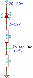
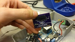
No problems there. This works okay, but we lose a lot of precision, as only ~1/3 of the Arduino’s range is actually used: the Arduino’s ADC has 1024 different readings between 0-5V, so when reading the 0-30V range the precision is just about 30V / 1024 \approx 0.03 V over the range. If only we could move the lower bound, so that 20V would map to 0V on the Arduino. A wild Zener Diode appears! One use of a Zener diode is as a voltage shifter. voltageshifter Zener diode voltage shifter. This work is licensed under the Creative Commons Attribution 3.0 License, https://en.wikipedia.org/wiki/File:VoltageShifter2.png. The closest Zener diode I could find was an 18V of the BZX79 series. This resulted in the following circuit: zener-voltage-divider which I hacked into my Arduino box. Hacked supply monitoring Now, theoretically the formula for translating an voltage at the Arduino to the supply voltage should be:

    \[Vcc = V_{in} / (4700/(4700+6800)) + 18 = V_{in} \cdot 2.4468 + 18\]

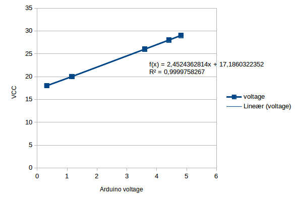
I then did some quick measurements of various input voltages and the resulting voltage at the Arduino pin:
Input voltage Arduino pin
18V 0.32V
20V 1.16V
26V 3.60V
28V 4.41V
29V 4.81V
Plot it into a spreadsheet, create a graph and add a linear regression gives: Now, this formula is a bit different compared to the theoretical one, mainly in the Zener diode drop. However, the datasheet for the BZX79 actually has the 18V C-type (\plusminus 5\%) as between 16.8-19.1V, so this is well within spec. Since this is just a one-off, I’m happy to just use the measured formula, as this will be more accurate. The final precision should be 12V / 1024 = 0.012V. The current should be around I = \frac{U}{R} = 30V/11500 Ohm \cdot 1000 \frac{mA}{A} = 2.6mA, which again is ok.

Gemt under: Extern, HAL9k

Tags: ,

17 jun

0 Comments

Roomba 500-series Easy Scheduling using an Arduino

Af

DSC_0879
I have a iRobot Roomba 500-series vacuum cleaner robot, but without any remote, or command center or anything; alas, I have to push a button everytime I want the cleaning revolution to start :-(

But no more! It turns out the Roomba can be programmed, quite easily, to schedule automatically, and all you need is:

  • 1 Arduino
  • 2 wires

The Roomba actually supports a serial protocol, the iRobot Roomba 500 Open Interface Specification, that allows remote control, driving, sensoring, and scheduling.

Finding the serial port

Remove the plastic cover. It is easiest to remove the vacuum bin, and carefully pry it off with a screwdriver.
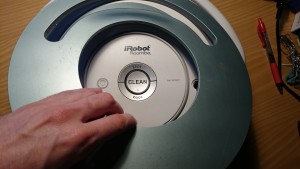
DSC_0882DSC_0884

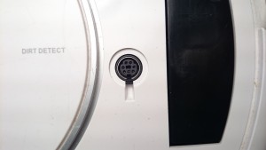
There should be a 7-pin plug, on the right side. It has the following pinout:
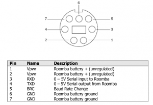
Roomba serial pinout

Roomba serial pinout

Program the Arduino

Use this sketch (download: roombaschedule.ino):


/*
Set a schedule on an iRobot Roomba 500 series, using just an Arduino.
Mads Chr. Olesen, 2015.
*/

const byte currentDay = 3;
// 0: Sunday, 1: Monday, 2: Tuesday, 3: Wednesday, 4: Thursday, 5: Friday, 6: Saturday
const byte currentHour = 2;
const byte currentMinute = 58;

// Schedule
const byte SUNDAY = 0x01, MONDAY = 0x02, TUESDAY = 0x04, WEDNESDAY = 0x08, THURSDAY = 0x10, FRIDAY = 0x20, SATURDAY = 0x40;

const byte daystorun = SUNDAY | MONDAY | WEDNESDAY | FRIDAY;
const byte times[14] = {
3, 0, // Sunday time
3, 0, // Monday time
3, 0, // Tuesday time
3, 0, // Wednesday time
3, 0, // Thursday time
3, 0, // Friday time
3, 0, // Saturday time
};

const int ledPin = 13;

void setup() {
Serial.begin(115200);
pinMode(ledPin, OUTPUT);
digitalWrite(ledPin, 0);

Serial.write(128); //Start
delay(1000);
Serial.write(131); //Safe mode, turns off Roomba light
delay(1000);
Serial.write(128); //Start, back to passive mode
delay(500);

//Set day time
Serial.write(168);
Serial.write(currentDay);
Serial.write(currentHour);
Serial.write(currentMinute);
delay(500);

//Set schedule
Serial.write(167);
Serial.write(daystorun);
for (int i = 0; i < 14; i++) {
Serial.write(times[i]);
}
}

void loop() {
digitalWrite(ledPin, 1);
delay(1000);
digitalWrite(ledPin, 0);
delay(1000);
}

You need to modify the variables at the top: set currentDay, currentHour, currentMinute according to the present time.
The pre-programmed schedule is to clean at 03:00 on Sunday, Monday, Wednesday and Friday. You can change this if you wish, by altering the daystorun and times variables.

If you don't modify the schedule, the Roomba should start automatically after 2 minutes.

Put it all together

You should now have a partially undressed Roomba, and a programmed Arduino. Now it is time to connect them. With both unpowered, connect the following:

  • Arduino GND to Roomba ground (pin 6)
  • Arduino TX (pin 1 on e.g. Uno) to Roomba RX (pin 3)

It should look like this:
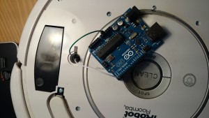
DSC_0886

Now, the moment of truth. Press the "CLEAN" button on the Roomba, the light should go on. Plug in the USB for the Arduino. The Roomba light should turn off briefly, and after a few seconds the Arduino should blink it's LED. The schedule is now programmed, all done!

Gemt under: Extern, HAL9k

Tags: ,

06 maj

0 Comments

Indkaldelse til Ordinær Generalforsamling i Hal9k torsdag 2014-05-15 kl. 19:30
Af

Følgende er dagsordenen til den ordinære generalforsamling i foreningen HAL9k torsdag 2014-05-15 kl. 19:30 på Sofiendalsvej 80, 9200 Aalborg SV.

Inden generalforsamlingen er der fællesspisning ca. kl. 18.30. Tilmelding til spisning (menu/pris ikke kendt endnu, forventet max 50,-) foregår på https://doodle.com/xgcy9i9nd77s95z6 af hensyn til antallet.

Dagsorden:
1. Valg af ordstyrer.
2. Valg af referent.
3. Valg af to stemmetællere.
4. Bestyrelsesformanden og kassereren aflægger beretning, samt præsenterer planer for den kommende sæson.
5. Kassereren fremlægger det reviderede regnskab til godkendelse.
6. Forslag fra bestyrelsen eller medlemmerne, herunder vedtægtsændringer, behandles.
  – Forslag om nedsættelse af kontingent fra sidste generalforsamling:
100kr pr. md, (75kr for stud.).
7. Behandling af eksklusionssager.
8. Valg af revisor.
9. Valg af bestyrelse.
10. Valg af op til to suppleanter.
11. Behandling af indkommende forslag.

Indkomne forslag skal være bestyrelsen i hænde senest syv dage før generalforsamlingen.

Vi hackes ved,  

Bestyrelsen Hal9k

Gemt under: Projekter

03 apr

0 Comments

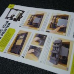
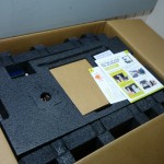
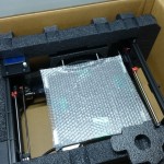
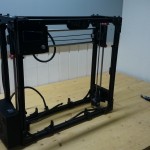
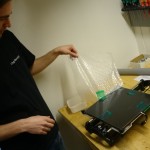
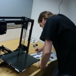
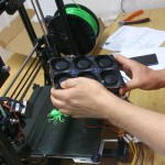
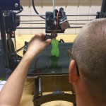
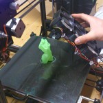
LulzBot Unboxing

Af


Gemt under: Projekter

17 jan

Kommentarer lukket til Reparere billige Denver Wake-up lampe

Reparere billige Denver Wake-up lampe

Af

Jeg havde to billige wake-up lamper fra Harald Nyborg der begge fejlede med samme symptomer: lyset var permanent tændt så snart strømmen var sat til, i stedet for at kunne slukkes og dæmpes. Grunden til nr. 2 blev købt var at nr. 1 fejlede efter garantien udløb, og til 200,- kunne det jo knapt betale sig at kigge på det. Da nr. 2 fejlede med samme symptom blev jeg stædig og irriteret over kun at kunne lave “brug-og-smid-væk”.

Hvor svært kunne det være at reparere noget billigt Kina-skrammel? Ikke ret svært viste det sig. Skidtet blev åbnet, og viser ret tydeligt hvor meget kvalitet man får for ikke ret mange penge:
Billigt print
Efter lidt konsultation af nogle af de mere elektronik-kyndige fik vi lokaliseret fejlen til en Triac der nok var brændt af. Desværre havde producenten valgt at slibe teksten af, så det var umuligt at se hvilken chip det var (sådan noget svineri!) — det virkede dog heldigvis med en helt standard BT137. På den ene lampe var der også brændt en modstand af: den var helt forkullet, men heldigvis kunne vi se på den anden hvilken modstand det var.
Ny triac

Efter at have loddet ny triac og modstand på, virkede lamperne som nye 🙂

Kan det betale sig at reparere billigt Kina-skrammel der er gået i stykker? Måske ikke økonomisk, til gengæld risikerer man at lære noget. Og så er det jo ret fedt at kunne fixe ting selv, i stedet for kun at kunne købe og smide væk!

Gemt under: Projekter